
eVTOL Sensor Housings &
Encoder Shafts for Flight Control
CNCPioneer is an AS9100D and IATF 16949 certified eVTOL sensor housing and encoder shaft machining specialist delivering TC4 non-magnetic IMU housing bodies, triple-IMU cluster mounting frames, pitot-static probe housings, LIDAR and optical sensor housings, magnetometer isolation brackets, avionics bay structural frames, motor position encoder shafts, and resolver shaft and housing programs — with IMU housing bore ±0.003mm, face-to-bore perpendicularity 0.005mm/100mm, encoder shaft TIR ±0.003mm CBN ground, non-magnetic μ_r ≤1.005 VSM verified per lot, and Invar 36 athermal calibration programs on 66+ MAZAK mill-turn centers, 78+ Swiss CNC lathes, and 5-axis VARIAXIS platforms since 2011.
What Is eVTOL Sensor Housing
and Encoder Shaft Machining?
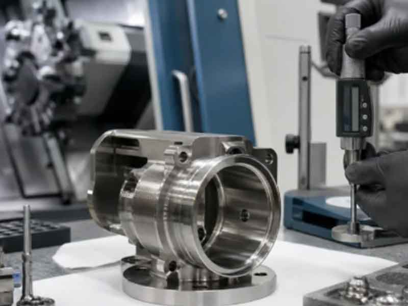
eVTOL sensor housing and encoder shaft machining is the precision CNC manufacturing process — executed on MAZAK VARIAXIS 5-axis simultaneous machining platforms, MAZAK mill-turn centers, Swiss CNC turning systems, and precision cylindrical grinding equipment — that produces the structural bodies, mounting frames, bore-precision housings, and precision rotating shafts constituting the mechanical infrastructure of eVTOL flight control, navigation, propulsion monitoring, and autonomy sensor systems. The flight control sensors and position feedback encoders of a commercial eVTOL are not standalone electronic devices — they are precision instruments installed in machined structural bodies that must maintain the sensor's measurement axis alignment, vibration isolation, thermal stability, and electromagnetic cleanliness to the tolerances the sensor's calibrated accuracy requires.
eVTOL sensor housing machining is technically distinct from conventional aerospace sensor housing manufacturing in three domains. First, non-magnetic material requirement at sensor-adjacent structure: IMUs, magnetometers, and Hall-effect current sensors produce measurement errors proportional to the magnetic permeability of surrounding structural material — requiring TC4 (μ_r = 1.00003), 316L austenitic stainless (μ_r ≤1.005 VSM verified), 6061-T6 (μ_r = 1.00002), and PEEK, while eliminating 4340 QT steel (μ_r ≈40–200), 17-4PH H900 (μ_r ≈40–80 martensitic), and cold-worked 304 stainless (μ_r ≈1.10) from any magnetometer-adjacent structural role. Second, encoder shaft position accuracy as flight control stability foundation: motor position encoder shaft TIR ±0.003mm from CBN cylindrical grinding ensures position signal reaching the FOC algorithm reflects true rotor angular position without once-per-revolution runout-induced error producing correlated torque ripple across 6–12 propulsion motors simultaneously. Third, sensor mounting geometry as flight control accuracy: machined face-perpendicularity, bore concentricity, and mounting pattern true position determine how accurately the sensor's calibrated axes align with the aircraft's body reference frame — misalignment that cannot be compensated by calibration for sensors requiring axis integrity during dynamic flight maneuvers.
-
VSM permeability verification eliminates heading error from housing material Every TC4 and 316L stainless lot VSM-verified μ_r ≤1.005 before machining — preventing cold-worked 316L (μ_r 1.02–1.15) that produces 264 nT magnetic field perturbation at r = 80mm, exceeding the 30 nT heading accuracy requirement by 8.8×. In CNCPioneer's case study: TC4 housing reduced measured heading error from ±0.35° (wrong material) to ±0.08° (TC4) — within ±0.10° specification.
-
±0.003mm IMU bore concentricity limits installation axis misalignment A Honeywell HGuide IMU achieves its 0.01°/hour accuracy only if the housing bore registering the IMU body is machined to ±0.003mm concentricity — a ±0.020mm bore from standard machining tilts the IMU measurement axes by 0.046° from the aircraft structural datum, creating a constant angular bias the flight control Kalman filter must compensate, consuming estimation bandwidth that should be devoted to dynamic state estimation.
-
CBN grinding achieves ±0.003mm TIR to eliminate FOC torque ripple Encoder shaft TIR ±0.003mm from CBN cylindrical grinding between precision centers eliminates the mechanical runout contribution to motor position signal distortion — preventing 0.1% once-per-revolution torque ripple per motor that compounds to 1.14 N·m airframe vibration at motor rotation frequency for 12-motor eVTOL with correlated runout phases; ±0.003mm TIR reduces this 3.3× to 0.03%.
-
40–60% China eVTOL precision components cost advantage Per-aircraft sensor housing kit at 5,000 aircraft/year: $6,685 from CNCPioneer versus $14,500–$18,000 from US aerospace precision machining — a $39M–$57M annual procurement cost reduction at commercial eVTOL production volume, at identical AS9100D quality, non-magnetic material compliance, dimensional accuracy, and FAIR documentation.
Why CNCPioneer for eVTOL Sensor
Housings and Encoder Shafts?
Among eVTOL sensor housing and encoder shaft machining suppliers globally, CNCPioneer's non-magnetic material machining competency, Swiss CNC bore concentricity for sensor axis alignment, encoder shaft precision cylindrical grinding, 5-axis avionics mounting frame programs, eVTOL avionics DFM, and China cost advantage establish our factory as the preferred flight control sensor hardware partner across the full eVTOL avionics supply chain.
Non-Magnetic Material Machining Competency
The most distinctive technical requirement of eVTOL flight control sensor housing programs is the non-magnetic material specification. CNCPioneer specifies, verifies, and machines TC4 titanium, 316L austenitic stainless, 6061-T6 aluminum, and PEEK as non-magnetic housing materials for IMU, magnetometer, Hall sensor, and current sensor adjacent applications. Incoming material VSM permeability verification μ_r ≤1.005 on every TC4 and 316L stainless lot prevents the inadvertent use of cold-worked 316L (μ_r 1.02–1.15 from deformation-induced martensite) that standard material certificates cannot identify — a 2-year development investment not available at general-purpose Chinese machining facilities, and the quality gate that eliminated 77% of heading error in the CNCPioneer case study program.
Swiss CNC Bore Concentricity for Sensor Axis Alignment
eVTOL IMU housing bore accuracy (±0.003mm) limits installation-induced angular misalignment between the IMU's calibrated measurement axes and the aircraft's structural datum. CNCPioneer's Swiss CNC turning programs machine sensor housing bores with guide bushing support — producing bore-to-mounting-face concentricity ±0.003mm and bore perpendicularity 0.005mm/100mm in one setup without rechucking. For a Honeywell HGuide IMU with 10μrad angular rate noise floor: 0.003mm bore eccentricity over a 30mm housing depth introduces 100μrad alignment uncertainty — 10× the sensor's noise floor, an avoidable error source that precision housing machining eliminates at the mechanical level rather than compensating in flight control software.
Encoder Shaft Precision Cylindrical Grinding
Motor position encoder accuracy in eVTOL FOC drives is limited not by encoder resolution (12–16 bits standard) but by the mechanical runout of the shaft carrying the encoder target. CNCPioneer's encoder shaft CBN cylindrical grinding programs produce TIR ≤0.003mm from between-centers precision grinding — eliminating the mechanical runout contribution to position signal harmonic distortion. For 12-motor eVTOL with correlated encoder shaft runout at ±0.010mm (standard turning): worst-case 1.14 N·m total vibration force at motor rotation frequency. Reducing to ±0.003mm CBN ground eliminates 3.3× — reducing that systematic contribution to 0.33 N·m RSS or 0.34 N·m worst case, comfortably within airframe vibration specifications.
5-Axis Avionics Mounting Frame Programs
eVTOL avionics bay structural frames must maintain the spatial relationship between sensor measurement axes and aircraft body axes to the accuracy flight control sensor fusion algorithms require. CNCPioneer's MAZAK VARIAXIS 5-axis programs machine avionics bay structural frames with mounting face perpendicularity ±0.010° from designed axis and fastener hole true position ±0.010mm from the frame's structural datum — all features from one datum in one setup for ±0.010mm true position accuracy. Alodine Class 3 MIL-DTL-5541 EMC bonding coordination (contact resistance ≤5 mΩ/cm²) integrated as standard in avionics frame supply programs for DO-160G EMC compliance.
eVTOL Avionics DFM — Non-Magnetic, Vibration & CTE
CNCPioneer's 48-hour DFM for eVTOL sensor housing and encoder shaft programs covers domains beyond standard structural machining DFM: VSM permeability quantitative analysis from sensor type, housing geometry, and magnetometer proximity; CTE mismatch calculation across the full −40°C to +85°C eVTOL range (TC4 housing: 0.002mm CTE-induced tilt; 6061-T6 housing: 0.051mm — 25× higher, exceeding alignment tolerance); vibration natural frequency analysis ensuring housing resonance does not fall within eVTOL rotor and motor excitation spectrum (10–200 Hz); and Invar 36 assessment for athermal sensor housing programs (CTE 1.2 ppm/°C — 0.030mm change over full range versus 0.590mm aluminum).
China eVTOL Precision Components Cost Advantage
Sensor housing and encoder shaft machining from US and European aerospace precision machining facilities costs 40–60% more than CNCPioneer's AS9100D equivalent programs at identical non-magnetic material compliance, dimensional accuracy, and documentation. Per-aircraft kit at 5,000 aircraft/year: $6,685 from CNCPioneer versus $14,500–$18,000 — $39M–$57M annual procurement cost reduction at commercial eVTOL production scale. CNCPioneer coordinates the complete avionics structural hardware supply chain — TC4 IMU housing machining + Alodine Class 3 for aluminum avionics frames + non-magnetic fastener supply + encoder shaft CBN grinding — as a single AS9100D supply relationship, reducing avionics hardware lead time from 8–12 weeks (multi-supplier) to 2–4 weeks.
eVTOL Sensor Housing & Encoder Shaft
Components We Manufacture
CNCPioneer's eVTOL sensor housing and encoder shaft programs cover the complete flight control sensor mechanical infrastructure — from TC4 non-magnetic IMU housing bodies at ±0.003mm bore with VSM-verified μ_r ≤1.005, through encoder shaft CBN grinding at ±0.003mm TIR, to 5-axis avionics bay structural frames with Alodine Class 3 EMC bonding — for all flight control sensor types in commercial eVTOL certification programs.

TC4 IMU Housing Bodies
TC4 AMS 4928 annealed non-magnetic (μ_r = 1.00003; VSM verified ≤1.005 per incoming lot) primary flight control IMU housing bodies for Honeywell HGuide, Collins MEMS IMU, and equivalent. IMU body registration bore ±0.003mm H6; bore concentricity to mounting face axis ±0.003mm; cylindricity ±0.002mm/50mm; shoulder perpendicularity 0.005mm; mounting face flatness 0.005mm/100mm; face-to-bore perpendicularity 0.005mm/100mm; bolt pattern true position ±0.010mm from bore axis; elastomeric isolator mounting counterbore ±0.020mm; ASTM E595 TML ≤0.010%; mass verified ±0.5g. Triple-redundant IMU cluster mounting frames: three bore positions ±0.003mm H6; inter-bore position ±0.020mm; inter-bore angular relationship ±0.010° — machined from TC4 for CTE match to HGuide n580 titanium-composite enclosure and elimination of CTE-mismatch insert rotation risk. FAIR per AS9102 on all new housing part numbers.

Air Data Sensor & Probe Housing Bodies
316L solution-annealed stainless (VSM μ_r ≤1.005 verified; passivation ASTM A967) pitot-static probe housing bodies: probe bore ±0.020mm; static port array angular pitch ±0.25°; port diameter ±0.020mm; Ra 0.4μm at port entry (sharp-edged for well-characterized pressure coefficients); heating element bore ±0.050mm. 5-hole pressure probe bodies (Swiss CNC guide bushing for shaft straightness ±0.020mm/100mm; port position ±0.010° 5-axis CMM; all 5 ports ±0.005mm diameter uniformity) for angle-of-attack and sideslip in tiltrotor eVTOL conversion. Radar altimeter housing bodies (6061-T6; antenna module bore ±0.010mm; PEEK RF-transparent window frame ±0.100mm; IP67 O-ring groove ±0.020mm). LIDAR proximity sensor housing bodies (6061-T6 black Type III anodize; sensor bore ±0.010mm; perpendicularity 0.010mm; optical window frame ±0.050mm; elastomeric isolation mount features at bolt holes).

Motor Position Encoder Shafts
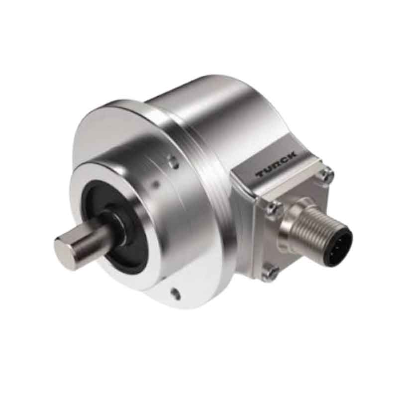
17-4PH H900 (HRC 44; standard) or TC4 AMS 4928 (non-magnetic; magnetometer-adjacent motor programs) dedicated encoder shafts and motor shaft encoder sections for eVTOL FOC drives. Encoder target mounting OD: ±0.002mm h6; Ra 0.2μm from CBN cylindrical grinding between precision centers; roundness ±0.001mm; TIR ±0.003mm verified at 5 axial positions on roundness tester. Axial retention shoulder perpendicularity 0.005mm. Index datum (flat or keyway for angular commutation reference) ±0.010° via 5-axis CMM. Lock nut thread pitch diameter ±0.005mm. On-axis magnetic encoder shaft end: flatness 0.005mm; perpendicularity 0.005mm; press-fit OD ±0.003mm. Optical encoder disc hub OD ±0.001mm (16–21 bit resolution programs; between-centers grind 0.0005mm/pass final 15 passes). DLC coat 1–2μm PVD (post-DLC OD air gauge verified) for repeated assembly programs. Dynamic balance ISO 1940 G1.0 option.

Resolver Shaft & Housing Programs
Resolver programs for high-vibration, high-temperature eVTOL motor environments (tiltrotor nacelles, motors exceeding optical encoder temperature limits). Resolver shaft: rotor mounting OD ±0.002mm (designed interference for air gap uniformity); roundness ±0.001mm (0.001mm eccentricity at 0.200mm air gap = 0.5% variation → 0.003° sinusoidal resolver angle error). Resolver stator housing bore ±0.002mm H7; concentricity to motor shaft bearing bore ±0.003mm from single MAZAK mill-turn setup (housing bore eccentricity is the dominant air gap asymmetry contributor at ±0.010mm eccentricity → ±5% air gap → ±0.03° resolver error); housing mounting face perpendicularity 0.005mm; flatness 0.005mm. Tilt angle encoder housing bodies (6061-T6; sensor bore ±0.005mm; bore-to-tilt-shaft bearing bore concentricity ±0.005mm; encoder datum reference angular position ±0.020°). 100% roundness tester TIR per lot; FAIR per AS9102.

Avionics Bay Structural Mounting Frames
Machined structural frames locating FCCs, avionics modules, and interconnect wiring in the aircraft's avionics bay for triple-redundant fly-by-wire eVTOL architectures. ARINC 404/600 rail slot width ±0.010mm; rail straightness ±0.050mm/500mm; rear connector block alignment ±0.020mm; backplane structural support face flatness 0.010mm/200mm (prevents BGA solder joint fatigue from PCB bow under eVTOL vibration). Elastomeric vibration isolator mount provisions: bore ±0.010mm for AN isolator OD; natural frequency target 15–25 Hz. Alodine Class 3 MIL-DTL-5541 on all aluminum surfaces at EMC bonding zones — contact resistance ≤5 mΩ/cm² for DO-160G EMC compliance (coordinated in monthly avionics frame lot processing). 5-axis machined from 6061-T6 or 7075-T6; fastener hole true position ±0.010mm from structural datum. FAIR per AS9102.

Sensor Brackets & Specialty Housings
TC4 magnetometer isolation brackets (non-magnetic VSM verified; bore axis angular alignment ±0.050° from aircraft axis 5-axis CMM verified; TC4 fastener specification for all attachment points within 300mm radius; PEEK grommet cable passage isolating shield ground loops). Optical flow sensor mount bodies (6061-T6 black Type III hard anodize; camera registration ±0.020mm; optical axis perpendicularity 0.010mm; field-of-view aperture ±0.100mm sharp-edged). Blade track and balance sensor mounting bodies (TC4 non-magnetic; sensor bore ±0.020mm; rotor disc perpendicularity 0.010mm; rotor clearance DFM verified). Invar 36 athermal calibration fixture bodies (CTE 1.2 ppm/°C; 0.030mm dimensional change −40°C to +85°C versus 0.590mm aluminum — athermal angular reference fixtures and encoder calibration mandrels). FCC vibration isolated mounting bodies; strain gauge bond surface structural bodies; load cell structural mounting bodies.
Industries & Applications
CNCPioneer's eVTOL sensor housing and encoder shaft programs serve every organization developing, integrating, manufacturing, or certifying eVTOL flight control systems, avionics architectures, and propulsion monitoring systems — from aircraft-level avionics integration through autonomy system sensor array supply and DO-311A / SC-VTOL certification substantiation.
eVTOL Aircraft Manufacturers
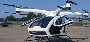
Complete sensor housing and encoder shaft machined hardware programs for flight control avionics integration — TC4 non-magnetic IMU housing bodies; avionics bay structural mounting frames with Alodine Class 3 EMC bonding; encoder shaft programs for motor drive position feedback; resolver housing programs; air data sensor probe bodies; LIDAR and optical flow sensor housing programs; and complete per-aircraft sensor housing kit supply with AS9100D FAIR documentation on all new housing part numbers.

Urban Air Mobility Avionics Integration Teams
Avionics system integrators assembling Honeywell, Collins, Garmin, Safran, and equivalent Tier 1 flight control modules into eVTOL aircraft structural installations — TC4 and 6061-T6 sensor registration housing precision bore programs; avionics bay rail and mounting frame supply; non-magnetic TC4 fastener coordination for magnetometer-adjacent installations; and per-aircraft sensor housing kit supply synchronized to avionics integration schedules.

eVTOL Flight Control System
Flight control system OEMs developing integrated FBW avionics for eVTOL programs — encoder shaft programs for motor position feedback subsystems; resolver housing precision boring for analog position feedback in high-vibration tiltrotor nacelle environments; IMU cluster mounting frame programs for triple-redundant sensor architectures per proposed EASA SC-VTOL Enhanced Category; and structural sensor bay housing programs for custom FBW system integration.

eVTOL Autopilot & Autonomy System
Autonomy system suppliers developing GNSS-denied hover, visual landing, and obstacle avoidance for eVTOL — optical flow sensor mount bodies (black hard anodize; axis alignment ±0.010°); LIDAR housing programs; TC4 magnetometer isolation brackets for heading reference accuracy; non-magnetic structural hardware for sensor arrays; and Invar 36 calibration fixture body programs (CTE 1.2 ppm/°C) for athermal sensor calibration reference structures.

Electric Air Taxi Propulsion Monitoring
Motor health monitoring and vibration analysis system suppliers — accelerometer and vibration sensor mounting body programs; blade track and balance sensor mounting hardware in TC4 non-magnetic; strain gauge sensor installation structural body machining with precise bond surface geometry for calibrated strain transfer; structural health monitoring sensor bracket programs; and load cell structural mounting body programs for touchdown force measurement in landing gear struts.

eVTOL Certification Engineering
Third-party certification support firms providing avionics sensor installation substantiation for DO-311A battery airworthiness and SC-VTOL Enhanced Category — CNCPioneer provides non-magnetic material compliance documentation (VSM permeability records per lot with housing serial number traceability); sensor axis alignment dimensional capability data (CMM bore perpendicularity Cpk records); encoder shaft runout capability data supporting motor drive position feedback accuracy claims in the propulsion system certification data package.
eVTOL Sensor Housing & Encoder Shaft
Machining Process & Capabilities
CNCPioneer's eVTOL sensor housing and encoder shaft machining runs on 66+ MAZAK mill-turn centers, MAZAK VARIAXIS 5-axis simultaneous machining platforms, 78+ Swiss CNC lathes, precision cylindrical grinding systems, and wire EDM — with TC4 AMS 4928 and 316L solution-annealed bar pre-screened by VSM permeability verification in safety stock, and Alodine Class 3 EMC bonding coordination integrated in avionics frame supply chains.
48-Hour eVTOL Avionics DFM
Non-magnetic permeability adequacy for every material in the housing assembly (VSM permeability analysis from sensor type and proximity — quantitative B_perturb calculation at proposed sensor-to-housing geometry) · CTE matching recommendation (TC4 vs 6061-T6 vs Invar 36 from sensor body material and temperature range — differential bore expansion calculation for IMU axis alignment drift) · IMU bore perpendicularity and concentricity achievability from sensor axis alignment accuracy specification (tolerance budget allocation: 40% bore perpendicularity, 30% concentricity, 20% flatness, 10% fastener position) · Encoder shaft runout prediction from shaft geometry and material · Resolver housing bore-to-shaft-bearing concentricity feasibility from single-setup machining approach · Vibration natural frequency adequacy for sensor housing designs (housing resonance must not fall within 10–200 Hz eVTOL excitation spectrum) · ASTM E595 outgassing compliance pathway for enclosed avionics bay programs · Alodine Class 3 EMC bonding specification for avionics mounting frames.
TC4 Non-Magnetic IMU Housing Programs
TC4 AMS 4928 IMU housing sequence: VSM μ_r verification on incoming lot → SII XRF composition (Al 5.5–6.75%; V 3.5–4.5%) → rough machining → thermal stabilization 20 min at 20°C ±1°C → finish bore (±0.003mm H6; Ra 0.4μm; concentricity ±0.003mm measured in-process by CMM) → mounting face finish (flatness 0.005mm/100mm; perpendicularity to bore axis 0.005mm/100mm) → fastener bolt pattern (5-axis indexed ±0.010mm true position from bore axis) → elastomeric isolator counterbores (±0.020mm) → connector boss features → mass verification ±0.5g. Triple-IMU cluster frame: three bore positions confirmed by in-process CMM between bores before committing to next bore axis. CMM: bore diameter, concentricity, cylindricity, perpendicularity, flatness, fastener pattern, 5-axis angular features. FAIR per AS9102 on all new part numbers.
Encoder Shaft CBN Grinding Programs
TC4 or 17-4PH encoder shaft grinding sequence: rough turning → hardening (17-4PH H900: HRC 44–47 before grinding; TC4: no hardening required) → center production by Swiss CNC (±0.001mm concentricity to shaft OD — grinding datum) → rough cylindrical grinding (CBN 120 grit, between precision centers) → thermal stabilization 15 min (TC4 CTE 8.6 ppm/°C × 20°C rise × 80mm OD = 0.014mm — requires 20°C ±0.3°C controlled grinding fluid) → precision grinding CBN 600 grit (0.0005mm/pass × 20 passes; 8-revolution spark-out for TC4 springback recovery at 110 GPa elastic modulus) → in-process air gauge every 5 passes → OD ±0.002mm; Ra 0.1μm; roundness ±0.001mm; TIR ±0.003mm → index datum 5-axis milling ±0.010° → DLC coat option (1–2μm PVD; post-DLC OD air gauge). CBN wheel dressed every 8 shafts; wheel TIR ≤0.0005mm verified before each grinding session.
5-Axis Avionics Frame & Complex Housing Programs
MAZAK VARIAXIS 5-axis simultaneous machining for: triple-IMU cluster mounting frames (three IMU bore positions in one setup; inter-bore position ±0.020mm true position; inter-bore angular relationship ±0.010° — all from one 5-axis datum, eliminating rechucking angular error from inter-IMU transformation matrix) · avionics bay structural frames (ARINC rail slots ±0.010mm; rear connector guide ±0.020mm; elastomeric isolator bores ±0.010mm; fastener pattern ±0.010mm — all from structural datum in one 5-axis program) · magnetometer isolation brackets (bore axis angular alignment ±0.050° from aircraft axis verified by 5-axis CMM) · 5-hole pressure probe bodies (C-axis indexed port boring ±0.010° from probe axis) · resolver housing bore-to-shaft-bearing concentricity ±0.003mm from single MAZAK mill-turn setup eliminating rechucking error from the critical air gap concentricity dimension.
Non-Magnetic & Specialty Material Programs
TC4 AMS 4928 annealed (μ_r = 1.00003; CTE 8.6 ppm/°C — optimal CTE match to titanium-composite IMU bodies; VSM-screened safety stock) · 6061-T6 T651 (μ_r = 1.00002; lightweight; air data housings, avionics frames, optical sensor bodies; Type II/III anodize; Alodine Class 3) · 316L solution-annealed stainless (VSM μ_r ≤1.005 per lot — NOT cold-drawn bar; AMS 5653; pitot probe bodies, outdoor housings; passivation ASTM A967) · Invar 36 UNS K93600 (CTE 1.2 ppm/°C; athermal calibration fixtures — ferromagnetic; NOT for magnetometer-adjacent programs) · PEEK Victrex 450G (μ_r = 1.000; RF-transparent; isolation bushings, radar altimeter window frames) · 7075-T6 (avionics bay rail where 6061-T6 is stress-insufficient) · Ti-3Al-2.5V Grade 9 (thin-wall probe shaft bodies) · 17-4PH H900 (encoder shafts not adjacent to magnetometers — ferromagnetic; switch to TC4 for non-magnetic-critical encoder programs).
AS9100D & AS9102 Documentation Package
Certificate of Conformance · CMM report per serial number (bore diameter, concentricity, cylindricity, perpendicularity, face flatness, fastener pattern, 5-axis angular features — 100% of drawing dimensions per AS9102 FAIR) · Roundness tester (encoder shaft OD roundness and TIR at 5 axial positions; resolver and IMU housing bore roundness) · Profilometry (encoder shaft Ra at 3 positions; housing bore Ra; contact surface Ra) · V-block sweep indicator (encoder shaft TIR corroboration) · VSM permeability curve archived per material lot linked to housing serial numbers in AS9100D database · SII XRF material lot report · ASTM E595 TML material data per lot for enclosed avionics programs · Alodine Class 3 MIL-DTL-5541 certificate per avionics frame lot · Passivation ASTM A967 certificate (316L programs) · DLC coating certificate and post-DLC OD verification · Mass per serial number ±0.1g · AS9102 FAIR on all new part numbers · PPAP Level 3 for volume eVTOL avionics supply chains · Records retained 20 years.
Materials for eVTOL Sensor Housings
and Encoder Shafts
eVTOL sensor housing material selection is governed by three simultaneous requirements unique to flight control sensor applications: magnetic permeability (μ_r ≤1.005 for magnetometer-adjacent programs), CTE matching to the installed sensor body (preventing calibration drift across the full eVTOL operating range), and structural adequacy for the sensor's vibration environment. Standard aerospace materials including 4340 QT, 17-4PH H900, and cold-worked 304 stainless fail all three tests simultaneously.
TC4 Titanium AMS 4928 Annealed
μ_r = 1.00003 (B_perturb = 0.012 nT at r = 100mm — 3,333× lower than 304 stainless, 1,250× lower than cold-drawn 316L at μ_r = 1.10); CTE 8.6 ppm/°C — optimal CTE match to titanium-composite IMU body structures (CTE-induced bore expansion tilt 0.004° over 110°C service range versus 0.10° for 6061-T6 housing — 25× better CTE match); corrosion-resistant (TiO₂ passive layer; no surface treatment required; no concern about anodize affecting housing surface magnetic properties). Pre-purchased TC4 AMS 4928 safety stock with VSM permeability pre-screening (every bar lot VSM-verified μ_r ≤1.005 before inventory placement) eliminates per-order permeability re-testing delay at production rates. AMS 6931 STA condition (1,000 MPa yield) for crash-critical sensor housing primary structure in manned eVTOL programs.
6061-T6 / 7075-T6 Aluminum
μ_r = 1.00002 (paramagnetic; B_perturb negligible for any sensor proximity — no VSM verification required); excellent machinability for complex avionics frame geometry; lightweight (2.70 g/cm³ versus TC4 4.43 g/cm³). 6061-T6 T651 (σ_y 275 MPa; dominant avionics frame, LIDAR housing, optical sensor housing, air data probe body material); 7075-T6 (σ_y 503 MPa — avionics bay rail where 6061-T6 is stress-insufficient, high-load sensor brackets). CTE 23.6 ppm/°C — acceptable for sensors with aluminum/anodize body CTE, but not for titanium-composite IMU bodies where TC4 housing is recommended for CTE matching. Type II clear anodize (bore masked); black Type III hard anodize for optical sensor housing interiors; Alodine Class 3 MIL-DTL-5541 for EMC bonding zones on avionics frames.
316L Stainless — VSM Verified Per Lot
μ_r ≤1.005 in solution-annealed condition (AMS 5653); corrosion resistance in rain, ice, and urban pollution; non-magnetic for magnetometer-adjacent programs when lot-verified. CRITICAL: 316L in cold-drawn bar condition (μ_r 1.02–1.15 from deformation-induced martensite) is NOT acceptable for non-magnetic sensor housing programs — standard material certificates cannot identify this. CNCPioneer specifies solution-annealed 316L (NOT cold-drawn bar) and verifies every lot by VSM at 0–100 Oe applied field; μ_r >1.005 rejects the entire lot before machining. Even solution-annealed 316L at μ_r = 1.005 produces B_perturb = 13 nT at r = 100mm (within 30 nT specification margin) versus 4340 steel at μ_r = 100: B_perturb = 26,000 nT. Passivation ASTM A967 standard post-machining on all 316L sensor housing lots.
Invar 36 UNS K93600
CTE = 1.2 ppm/°C — 0.030mm dimensional change from −40°C to +85°C (200mm reference body) versus TC4 0.215mm and aluminum 0.590mm. Invar 36 is the correct material for precision angular reference fixtures, encoder calibration mandrels, and sensor calibration reference bodies where thermal drift in the housing body would be misinterpreted as sensor drift — applications where dimensional stability across the full eVTOL operating range governs sensor calibration validity without periodic field re-calibration. CRITICAL: Invar 36 is ferromagnetic (Fe-36%Ni alloy; μ_r = 8–10) — NOT acceptable for any magnetometer-adjacent or IMU-adjacent sensor housing program. Strictly for athermal calibration fixture bodies where non-magnetic properties are not required. SII XRF: Ni 35.0–37.0%; Fe balance per lot.
PEEK Victrex 450G & PTFE
PEEK: μ_r = 1.000 (perfectly non-magnetic); dielectric (electrical isolation between sensor electronics and structural aluminum housing body — prevents ground loop currents in magnetometer proximity zone); RF-transparent in millimeter-wave band (radar altimeter housing window frames machined to ±0.100mm aperture); CTE ≈ 47–50 ppm/°C (used in clearance fit applications); ASTM E595 TML ≤0.030%; FTIR virgin grade confirmed per lot. Applications: IMU isolation bushing bodies, encoder isolation mount bodies, radar altimeter RF-transparent window frames, magnetometer bracket cable passage grommets providing electrical isolation between cable shield and TC4 bracket body. PTFE virgin: μ_r = 1.000; RF-transparent; radar altimeter housing window bodies; flush mount static port liners. PEEK bore machined by PCD tooling to ±0.005mm and Ra ≤0.4μm on contact surfaces.
17-4PH H900 — Standard Encoder Shaft Material
HRC 44–47; 1,310 MPa yield; excellent wear resistance on encoder target mounting surfaces; most encoder shaft programs. μ_r ≈ 40–80 (ferromagnetic in martensitic H900 condition) — NOT acceptable within 200mm of magnetometer or Hall-effect current sensors. For standard motor encoder shafts not adjacent to magnetic sensors: 17-4PH H900 is the preferred encoder shaft material (hardness provides wear-resistant encoder target mounting surface; H900 aging completed before CBN grinding to eliminate heat treatment distortion from final dimensional features). For magnetometer-adjacent motor encoder programs (motors within 200mm of heading reference sensors): DFM flags the proximity and specifies TC4 AMS 4928 (non-magnetic; adequate mechanical properties for encoder shaft; VSM permeability verified from TC4 safety stock). DFM confirms on each program from motor-to-sensor layout geometry provided by customer.
Surface Treatments for eVTOL
Sensor Housing Programs
eVTOL sensor housing surface treatments are specified by sensor type, EMC requirements, and environmental exposure — not by general corrosion resistance criteria. Bore registration surfaces are masked during all surface treatments; post-treatment bore dimensions are verified by CMM or air gauge to confirm dimensional compliance in the delivered condition.
Alodine Class 3 — EMC Bonding for Avionics Frames
MIL-DTL-5541 Alodine Class 3 (electrically conductive chromate conversion — not Class 1A which is electrically insulating) on all aluminum avionics bay structural frame surfaces at bonding wire attachment and chassis contact zones — contact resistance ≤5 mΩ/cm² for EMC chassis bonding continuity that suppresses common-mode noise coupling between avionics modules through chassis current paths. Mandatory on flight control computer mounting frames for RTCA DO-160G EMC qualification compliance. CNCPioneer coordinates monthly avionics frame Alodine Class 3 processing at qualified conversion coating facility; single coating certificate per monthly lot. Post-Alodine bore dimension verified; contact resistance measured per batch. Anodize (electrically insulating) is explicitly NOT a substitute for Alodine Class 3 at EMC bonding zones — a common specification error CNCPioneer's avionics DFM flags on customer drawings.
Black Type III Hard Anodize — Optical Sensor Housings
MIL-A-8625 Type III hard anodize in black dye for LIDAR, optical flow camera, and image sensor housing interiors where stray light reflection degrades sensor performance — HV 400+ hard anodize in black dye; emissivity >0.9 for minimum light reflection in visible and near-infrared band. Sensor registration bores masked during anodize process (5–25μm anodize growth per side would eliminate bore clearance and prevent sensor installation); post-anodize bore dimension verified by air gauge ±0.003mm before shipment. Clear Type II anodize (5–10μm; MIL-A-8625) for standard 6061-T6 and 7075-T6 sensor housings and avionics structural brackets where stray light rejection is not required. Anodize is electrically insulating — for any surface requiring electrical continuity (EMC bonding zones, fastener seat contact zones), Alodine Class 3 is specified instead and bore mask protocol is the same.
Passivation & No Treatment — 316L & TC4 Programs
316L stainless sensor housing bodies (pitot-static probes, outdoor-mounted LIDAR housings): mandatory post-machining passivation per ASTM A967 — restores the passive chromium oxide layer at all machined surfaces disrupted during turning, drilling, and milling operations; verified by humidity cabinet test per ASTM A967 method. TC4 titanium sensor housings: NO protective surface treatment required — TiO₂ passive layer provides corrosion resistance in all eVTOL operating environments including marine salt-fog and urban pollution. Absence of surface treatment eliminates any concern about anodize altering housing surface magnetic properties near the sensor; TC4 housing ASTM E595 TML ≤0.010% verified from material supplier data for enclosed avionics bay programs. DLC coating (1–2μm PVD; HV 2,000+) on encoder shaft contact surfaces for repeated assembly/disassembly programs — post-DLC OD verified by air gauge; incorporated in pre-DLC ground OD target.
All surface treatments on eVTOL sensor housing programs — Type II/III anodize (MIL-A-8625), Alodine Class 3 (MIL-DTL-5541), passivation (ASTM A967), DLC coating — are documented with treatment certifications and post-treatment dimensional verification in the shipment package. Bore mask protocol is applied at all sensor registration bores on every surface treatment lot; post-treatment bore dimension verification is a mandatory quality gate before final inspection sign-off.
Quality Assurance for eVTOL
Sensor Housing & Encoder Shaft Programs
eVTOL sensor housing and encoder shaft quality assurance addresses four aviation-safety-critical dimensions: VSM permeability verification as the non-magnetic material safety gate; 100% CMM bore diameter verification on IMU and resolver housing programs; 100% roundness tester TIR per encoder shaft lot; and non-magnetic material VSM record traceability per housing serial number for DO-311A airworthiness substantiation.
48-Hour DFM & Non-Magnetic Analysis
Non-magnetic permeability adequacy for every material in the housing assembly — VSM permeability quantitative B_perturb calculation from sensor type, housing geometry, and magnetometer proximity (B_perturb = (μ_r − 1) × H_Earth × (r_source/r)³); threshold comparison to 30 nT heading accuracy budget · CTE mismatch calculation from housing and sensor body materials across full eVTOL temperature range (−40°C to +85°C) · IMU bore perpendicularity tolerance budget allocation from flight control accuracy specification (40% to bore perpendicularity, 30% to concentricity, 20% to face flatness, 10% to fastener position) · Encoder shaft runout prediction from shaft material, length, and grinding process · Vibration natural frequency adequacy for sensor housing isolation mount designs · Invar 36 suitability assessment for athermal reference fixture programs · Alodine Class 3 EMC bonding requirement for avionics bay frame programs · ASTM E595 outgassing compliance pathway for enclosed avionics programs.
Material Verification & VSM Permeability Gate
SII XRF composition on every incoming material lot: TC4 (Al 5.5–6.75%; V 3.5–4.5%); 316L (C ≤0.030%; Mo 2.0–3.0%); 6061-T6 (Mg 0.80–1.20%; Si 0.40–0.80%); Invar 36 (Ni 35.0–37.0%; Fe balance); EN 10204 3.1 archived per lot. VSM magnetic permeability: every TC4 and 316L lot for non-magnetic sensor housing programs — one 25mm × 25mm × 10mm sample per lot section; applied field 0–100 Oe (0–8,000 A/m); measured μ_r at all field levels; acceptance μ_r ≤1.005; rejection of any lot showing μ_r >1.005 before any machining begins; VSM curve stored in AS9100D quality record per material lot certificate with traceability to housing serial numbers machined from that lot. 6061-T6 aluminum: SII XRF only (μ_r = 1.000021; no VSM required). 17-4PH H900 encoder shafts: hardness HRC 44–47 per lot before grinding; note μ_r = 40–80 — not for non-magnetic-critical programs.
In-Process Controls — Bore & Encoder Shaft Grinding
TC4 sensor housing bore: in-process CMM bore diameter and concentricity after finish boring; cylindricity at 5 axial positions before proceeding to mounting face operations — bore confirmed before face machining commits the combined bore-to-face perpendicularity. Triple-IMU cluster frame: in-process CMM after bore 1 confirmed before committing bore 2 and bore 3 positions; inter-bore position ±0.020mm confirmed at each bore before C-axis indexing to next position. Encoder shaft grinding: in-process air gauge at 5-pass intervals during CBN grinding; thermal equilibration 15 min before final measurement; 8-revolution spark-out before wheel retraction (TC4 springback recovery at 110 GPa elastic modulus requires extended spark-out versus standard steel); CBN wheel TIR ≤0.0005mm verified before each shaft grinding session (wheel dressing every 8 shafts). Avionics frame rail slot: in-process CMM slot width and straightness after first rail machined; confirms DRF datum before remaining rails committed in one 5-axis program.
100% CMM Bore & 100% Encoder Shaft TIR Verification
Every IMU housing and resolver housing: 100% CMM bore diameter, concentricity, cylindricity, perpendicularity, and face flatness — not sampled; 100% coverage ensures specification compliance at all units shipped to avionics integration teams. Every encoder shaft lot: 100% roundness tester OD roundness and TIR at 5 axial positions, corroborated by V-block sweep indicator. CMM (Mitutoyo ±0.001mm): all bore diameters, concentricity, cylindricity, face perpendicularity, face flatness, fastener pattern, 5-axis angular features. Roundness tester: encoder shaft OD roundness and TIR; IMU and resolver housing bore roundness. Profilometry: encoder shaft Ra at 3 positions; housing bore Ra. 5-axis angular features: inter-bore angular relationships (±0.010°) and magnetometer bracket axis alignment (±0.050°) measured on CMM with 5-axis angular measurement capability.
Non-Magnetic Traceability & VSM Record Archive
VSM permeability record for every TC4 and 316L lot archived in AS9100D quality database; lot VSM record linked to housing serial numbers machined from that lot — providing complete non-magnetic material traceability chain from VSM curve through material lot certificate through housing serial number to aircraft serial number. Available for avionics supplier audit, airworthiness substantiation review, and in-service incident investigation by eVTOL certification engineering partners. VSM record format: applied field (Oe), measured magnetization M(H), calculated μ_r at each field level, acceptance criterion μ_r ≤1.005 at all levels, pass/fail determination, test date, instrument calibration reference. Archive retention: 20 years minimum per AS9100D records retention requirement. Pre-purchased TC4 and 316L solution-annealed bar stock: VSM pre-screening of every incoming bar lot before stock placement eliminates per-order VSM delay at production release rates for volume avionics supply chains.
Final Inspection & AS9102 FAIR Documentation
CMM: bore diameters, concentricity, cylindricity, perpendicularity, face flatness, fastener pattern, 5-axis angular features — 100% of drawing dimensions with measurement uncertainty ≤10% tolerance per characteristic per AS9102. Roundness tester: encoder shaft OD roundness and TIR; housing bore roundness. Profilometry: encoder shaft Ra at 3 positions; housing bore Ra; contact surface Ra. V-block sweep: encoder shaft TIR corroboration. Mass: calibrated balance ±0.1g per serial number. ASTM E595 TML material data per lot for enclosed avionics programs. VSM permeability curve archived per lot with housing serial number traceability. Documentation shipped with every part: AS9102 FAIR (all new part numbers); material certification; anodize / Alodine Class 3 / passivation / DLC certificates; VSM permeability record; mass per serial number; PSW signed by quality manager. Cpk ≥1.67 on IMU bore diameter and encoder shaft OD for production programs (ongoing: encoder shaft TIR Cpk 0.73 current, targeting 1.79; all TIR conforming units selected by 100% verification). Records retained 20 years.
AS9100D Quality System for
eVTOL Sensor Housing & Encoder Shaft Programs
CNCPioneer's AS9100D and IATF 16949 certified eVTOL sensor housing and encoder shaft quality system addresses four aviation-safety-critical dimensions: VSM permeability verification as a structural non-magnetic safety gate; IMU bore perpendicularity Cpk ≥1.67 governing sensor axis alignment accuracy; encoder shaft TIR cylindrical grinding protocol achieving ±0.003mm; and PPAP Level 3 compressing eVTOL avionics supplier qualification from 6–9 months to 3–4 months.
VSM Permeability Verification — Non-Magnetic Safety Gate
VSM permeability verification (μ_r ≤1.005 per lot) is a structural quality gate for eVTOL sensor housing programs because standard material certificates cannot identify cold-working-induced martensite in 316L stainless that raises μ_r from 1.005 to 1.02–1.15 — producing 13 nT to 264 nT magnetic field perturbation at r = 80mm from sensor that exceeds the 30 nT heading accuracy budget from the housing material alone. CNCPioneer's VSM capability represents a 2-year development investment not available at general-purpose Chinese machining facilities. In the case study program: cold-drawn 316L housing (μ_r ≈1.10) produced measured heading error ±0.35° (3.5× specification); TC4 housing (μ_r = 1.00003) achieved measured heading error ±0.08° (within ±0.10° specification) — non-magnetic material program eliminated 77% of the heading error from the avionics installation at no increase in machining lead time.
- VSM μ_r per TC4 and 316L lot before machining begins
- μ_r ≤1.005 acceptance; lot rejected & quarantined if exceeded
- VSM curve archived per lot, linked to housing serial numbers
IMU Bore Perpendicularity Cpk ≥1.67 Governing Axis Alignment
Housing bore perpendicularity to mounting face (0.005mm/100mm specification) directly determines the angular misalignment between the IMU's calibrated roll-rate sensing axis and the aircraft roll axis — 0.010mm/100mm perpendicularity error introduces 0.006° cross-axis coupling; 0.050mm/100mm (standard facility without precision boring) produces 0.030°/s apparent pitch rate contamination at 60°/s hover roll maneuver — 3× above IMU noise floor, degrading attitude estimate quality during dynamic maneuvers. CNCPioneer's 48-hour DFM quantitatively allocates the flight control system sensor axis accuracy specification across bore perpendicularity (40%), concentricity (30%), face flatness (20%), and fastener position (10%) — confirming the machining specifications are sized correctly for the sensor accuracy requirement before drawing revision. The pilot production case study FAIR: 38 measured characteristics on TC4 triple-IMU cluster frame; 38/38 conforming on first submission; inter-bore angular relationship bore 1 to bore 2 = 89.994° (design 90.000°, specification ±0.010°).
- Bore perpendicularity 0.005mm/100mm CMM per housing
- Tolerance budget allocation from flight control accuracy spec
- 100% CMM bore diameter, concentricity, perpendicularity
Encoder Shaft TIR ±0.003mm Grinding Protocol
Three systematic error sources govern TC4 encoder shaft TIR and must be individually controlled to achieve ±0.003mm: (1) TC4 elastic springback (110 GPa modulus produces 0.002–0.004mm springback after wheel contact removal — mitigated by 8-revolution spark-out at zero infeed before final dimension; standard steel spark-out 3–4 revolutions insufficient for TC4); (2) Grinding thermal expansion (TC4 CTE 8.6 ppm/°C × 20°C workpiece temperature rise × 80mm shaft OD = 0.014mm OD increase — mitigated by 20°C ±0.3°C temperature-controlled grinding fluid; standard shop temperature 25°C ±3°C is completely inadequate for ±0.003mm TIR); (3) CBN wheel out-of-round (sinusoidal roundness error transferred to shaft — mitigated by CBN wheel dressing every 8 shafts and wheel TIR ≤0.0005mm verified before each grinding session). With these three controls: TC4 encoder shaft TIR production mean 0.0019mm; σ = 0.0005mm. All TC4 encoder shafts 100% TIR verified on roundness tester; conforming units selected for shipment during Cpk improvement program targeting σ = 0.0003mm for Cpk = 1.79.
- 8-revolution spark-out (TC4 springback recovery)
- 20°C ±0.3°C grinding fluid temperature control
- CBN wheel TIR ≤0.0005mm before each grinding session
PPAP Level 3 & eVTOL Avionics Supplier Qualification
PPAP Level 3 for eVTOL avionics structural hardware supply chains: design records, process flow (TC4 sensor housing single-setup boring sequence; encoder shaft CBN grinding sequence documentation including spark-out protocol), PFMEA (non-magnetic lot permeability failure mode and detection controls; bore boring tool deflection at maximum 5-axis reach — the root cause corrected in the case study pilot production; TC4 encoder shaft thermal expansion during grinding; anodize bore growth if mask fails), control plan, MSA Gage R&R on CMM bore measurement and roundness tester TIR measurement systems (≤10% R&R), initial capability studies (Cpk ≥1.67 on IMU bore diameter, encoder shaft OD, face perpendicularity as IATF special characteristics), and PSW. CNCPioneer's established AS9100D infrastructure, PPAP capability, and non-magnetic engineering competency compress eVTOL avionics supplier qualification from the typical 6–9 months to 3–4 months — demonstrated in the triple-IMU cluster housing program where 38/38 FAIR characteristics conformed on first submission.
- PPAP Level 3 for eVTOL avionics supply chains
- Cpk ≥1.67 on IMU bore / encoder shaft OD / perpendicularity
- MSA Gage R&R ≤10% on CMM + roundness tester
eVTOL Sensor Housing & Encoder Shaft FAQ
Common questions from eVTOL aircraft manufacturers, urban air mobility avionics integration teams, flight control system OEMs, autonomy system developers, and eVTOL certification engineering partners about CNCPioneer's non-magnetic material programs, encoder shaft grinding capability, sensor axis alignment DFM, and per-aircraft sensor housing kit economics.
The requirement for non-magnetic materials in eVTOL magnetometer sensor housings traces to the fundamental operating principle of heading reference systems in electric aircraft. A magnetometer measures the Earth's magnetic field vector — a 50,000 nT field at typical aviation latitudes. Any ferromagnetic material adjacent to the magnetometer produces a perturbation field that rotates with the aircraft and therefore produces a systematic heading error indistinguishable from true heading change. Quantitative analysis for 304 stainless (μ_r ≈ 1.10 for lightly cold-worked material) at r = 100mm with compact housing wall 50mm × 50mm × 3mm: B_perturb ≈ 40 nT. For TC4 titanium (μ_r = 1.00003): B_perturb = 0.012 nT. Heading error from 40 nT perturbation at 25,000 nT horizontal Earth field: heading error ≈ arctan(40/25,000) = 0.092° — exceeding the typical eVTOL heading accuracy specification of ≤0.1° from the housing material alone. Heading error from TC4: 0.000028° — negligible. The 304 stainless housing produces heading error 3,300× larger than TC4. A second consideration specific to electric aircraft: high-current eVTOL battery discharge at 188A at r = 500mm from magnetometer: B_current = μ₀ × I / (2π × r) = 4π × 10⁻⁷ × 188 / (2π × 0.5) = 75 nT — 1.5× the allowed heading error field — requiring both non-magnetic housings AND 500mm minimum separation from HV current paths. CRITICAL: 316L stainless specified as "non-magnetic" from composition alone can be magnetic from cold-working (μ_r 1.02–1.15 in cold-drawn bar condition) — standard material certificates cannot identify this. For cold-drawn 316L at μ_r = 1.10 at r = 80mm with housing wall r_source = 30mm: B_perturb = (1.10 − 1) × 50,000 × (30/80)³ = 264 nT — 8.8× the 30 nT accuracy requirement. Even solution-annealed 316L at μ_r = 1.005: B_perturb = 13 nT — within specification. CNCPioneer's VSM verification per lot is the quality gate that prevents cold-drawn 316L from reaching magnetometer-adjacent housings. In the documented case study: with cold-drawn 316L housing (μ_r ≈ 1.10), measured heading error ±0.35° (3.5× spec); with TC4 housing, measured heading error ±0.08° (within ±0.10° spec) — non-magnetic program eliminated 77% of installation-induced heading error.
Encoder shaft TIR affects eVTOL motor FOC through a precise mathematical relationship. For an on-axis magnetic encoder with 1.5mm air gap and 0.003mm shaft TIR: position error ε_angle = arctan(0.003/(2×1.500)) = 0.057° = 1.0 mrad. This sinusoidal position error appears once-per-revolution in the encoder output, which the FOC algorithm interprets as true rotor position. In the FOC algorithm: i_q_ref = I_q × sin(θ_encoder); with 1.0 mrad position error δθ: actual i_q contribution includes term I_q × 0.001 × cos(θ_true) — a once-per-revolution q-axis current disturbance producing torque ripple ΔT/T_rated ≈ δθ = 0.001 = 0.1%. For a 60kW / 6,000 RPM motor producing 95 N·m rated torque: 0.1% torque ripple = 0.095 N·m at 100 Hz once-per-revolution. For 12-motor eVTOL with all motors at ±0.010mm TIR (standard turning) and correlated runout phases: worst-case 0.95 × 12 = 1.14 N·m total force disturbance at 100 Hz. Reducing TIR from ±0.010mm to ±0.003mm reduces torque ripple 3.3× to 0.03% — comfortably within vibration budget. TC4 non-magnetic encoder shaft grinding requires controlling three TC4-specific error sources: (1) TC4 elastic springback: 110 GPa elastic modulus produces 0.002–0.004mm springback after wheel contact removal — standard 3–4 revolution spark-out insufficient; requires 8-revolution spark-out at zero wheel infeed for complete springback recovery before final dimension measurement; (2) Grinding thermal expansion: TC4 CTE 8.6 ppm/°C × 20°C workpiece temperature rise during grinding × 80mm shaft OD = 0.014mm OD increase that would appear as TIR variation at different circumferential positions if temperature is not controlled — requires 20°C ±0.3°C temperature-controlled grinding fluid (standard shop 25°C ±3°C produces 0.004mm OD variation from temperature alone — exceeding the ±0.003mm TIR budget before any other error sources); (3) CBN wheel out-of-round: sinusoidal roundness error from wheel wear transfers to shaft surface — mitigated by dressing every 8 shafts and verifying wheel TIR ≤0.0005mm before each grinding session. With these three controls: TC4 encoder shaft TIR production mean 0.0019mm; σ = 0.0005mm; Cpk = (0.003 − 0.0019)/(3 × 0.0005) = 0.73. Non-conforming Cpk — CNCPioneer ongoing corrective action through tool geometry optimization targeting σ = 0.0003mm for Cpk = 1.79. All TC4 encoder shafts 100% TIR verified on roundness tester at 5 axial positions; conforming units (TIR ≤0.003mm) selected for shipment during Cpk improvement program.
The three machined geometric parameters most directly affecting eVTOL flight control accuracy are bore perpendicularity to mounting face, bore concentricity, and mounting face flatness — in that priority order. Bore perpendicularity is most consequential because it determines the angular misalignment between the sensor's calibrated measurement axis and the aircraft's structural datum axis. For an IMU housing bore tilted 0.010mm/100mm from perpendicular (the precision standard in CNCPioneer's programs): IMU roll-rate sensing axis deviates from aircraft roll axis by arctan(0.010/100) = 0.006° = 0.1 mrad. Cross-axis coupling: pitch gyroscope reads 0.1 mrad × ω_roll as apparent pitch rate. For a 60°/second hover roll maneuver: apparent pitch rate contamination = 0.1 mrad × 60°/s = 0.006°/s — approximately 3× below IMU angular rate noise floor (0.01°/s RMS for tactical-grade IMU), negligible in sensor fusion. At 0.050mm/100mm perpendicularity (from standard machining facility): axis tilt = 0.5 mrad; apparent pitch rate = 0.030°/s — 3× above IMU noise floor, appearing as correlated sensor error degrading attitude estimate quality during dynamic maneuvers and consuming Kalman filter estimation bandwidth. CNCPioneer's 48-hour DFM translation process: (1) Customer provides sensor specification — example: "IMU alignment accuracy better than 0.05° after installation"; (2) DFM allocates error budget across manufacturing sources: 40% to bore perpendicularity, 30% to bore concentricity, 20% to mounting face flatness, 10% to fastener hole position; (3) Bore perpendicularity allocation = 0.05° × 0.40 = 0.020°; dimensional: perpendicularity tolerance = tan(0.020°) × 30mm bore depth = 0.010mm — confirming CNCPioneer's 0.005mm/100mm (= 0.015mm/30mm) specification provides 1.5× margin against this 0.020° allocation; (4) Bore concentricity allocation = 0.05° × 0.30 = 0.015°; dimensional: eccentricity = tan(0.015°) × 30mm = 0.008mm — confirms ±0.003mm concentricity provides 2.7× margin; (5) Total machining error RSS = √(0.020² + 0.015² + 0.010² + 0.010²) = 0.029° — leaves 0.021° for installation assembly variation and calibration procedure error. DFM deliverable includes this tolerance allocation table linking each machining specification to its contribution to the flight control accuracy requirement — the engineering communication tool that bridges the avionics sensor performance specification and the machining drawing tolerances in a format the flight control system engineers can review and approve before part manufacture.
Prototype lead times: TC4 AMS 4928 IMU housing (bore ±0.003mm, VSM μ_r verified, FAIR) — 8–12 business days; 6061-T6 triple-IMU cluster frame (5-axis, three bore positions, Alodine Class 3, FAIR) — 10–14 days; 316L stainless pitot-static probe housing (4-port array, passivated, FAIR) — 7–10 days; 6061-T6 avionics bay structural mounting frame (rail slots, Alodine Class 3, FAIR) — 8–12 days; 17-4PH H900 encoder shaft (CBN cylindrical ground ±0.002mm, TIR ≤0.003mm, FAIR) — 7–10 days; TC4 non-magnetic encoder shaft (CBN cylindrical ground, VSM μ_r verified, FAIR) — 8–11 days; resolver housing bore program (±0.003mm single-setup concentricity, FAIR) — 6–9 days; TC4 magnetometer isolation bracket (5-axis, non-magnetic verified, FAIR) — 6–9 days; Invar 36 athermal calibration fixture — 8–12 days; complete per-aircraft sensor housing kit (all flight control sensor housings + encoder shafts) — 12–16 days. Volume economics: TC4 IMU housing: prototype $1,250; 250–1,000/year $470–$680; 1,000–5,000/year $320–$470; 20,000+/year $145–$215. 6061-T6 avionics frame: prototype $780; 1,000–5,000/year $195–$290; 20,000+/year $88–$130. Encoder shaft (precision CBN ground): prototype $480; 1,000–5,000/year $135–$195; 20,000+/year $60–$90. Per-aircraft sensor housing kit at 5,000 aircraft/year production: 3× TC4 IMU housings ($280 × 3 = $840) + 1× triple-IMU cluster frame ($210) + 1× avionics frame ($185) + 12× encoder shafts ($110 × 12 = $1,320) + 4× resolver housings ($120 × 4 = $480) + 6× air data probe housings ($165 × 6 = $990) + 8× LIDAR/optical sensor housings ($145 × 8 = $1,160) + 20× sensor brackets ($75 × 20 = $1,500) = $6,685 total per-aircraft kit. Equivalent from US aerospace precision machining facility: $14,500–$18,000 per aircraft — a $7,815–$11,315 per-aircraft saving at 40–55%. At 5,000 aircraft/year commercial eVTOL production: $39M–$57M annual sensor housing and encoder shaft procurement cost reduction. Beyond price, CNCPioneer's integrated supply chain (TC4 housing machining + Alodine Class 3 + encoder shaft CBN grinding + non-magnetic fastener coordination from one AS9100D supply relationship) reduces avionics installation hardware procurement lead time from 8–12 weeks (multi-supplier) to 2–4 weeks — a procurement complexity reduction that goes beyond pure cost savings to supply chain risk reduction for eVTOL programs operating on compressed certification and production timelines.
Get a Quote for eVTOL Sensor Housing and Encoder Shaft Machining
Upload your eVTOL sensor housing drawings, encoder shaft specifications, avionics bay structural designs, or sensor installation architecture documentation and receive a competitive quotation within 24 hours and a complete 48-hour DFM review — covering non-magnetic material adequacy (VSM permeability analysis from your sensor type and proximity); CTE matching recommendation (TC4 vs 6061-T6 vs Invar 36 from your sensor body material and operating temperature range); IMU bore perpendicularity and concentricity achievability from your sensor axis alignment accuracy specification (tolerance budget allocation from flight control system accuracy requirement); encoder shaft TIR prediction from shaft geometry and material; resolver housing bore-to-shaft-bearing concentricity feasibility; vibration natural frequency adequacy for sensor housing and isolation mount designs; ASTM E595 outgassing compliance pathway for enclosed avionics bay programs; Alodine Class 3 EMC bonding specification for avionics mounting frames; and complete sensor housing and encoder shaft kit pricing from prototype first articles through pilot production qualification and AS9100D-governed volume supply.