
Humanoid Robot Leg Components Manufacturer
CNCPioneer is a precision humanoid robot leg components specialist and certified China humanoid robot leg components manufacturer delivering hip fork structural bodies, knee pivot brackets, ankle differential housings, and foot sole frames with structural interface angular accuracy of ±0.02°, fatigue-optimized fillet radius compliance of ±0.05mm, and mass verification to ±0.5g — 66+ MAZAK mill-turn and VARIAXIS 5-axis centers, 78+ Swiss CNC lathes, and dedicated wire EDM for humanoid robot OEMs and legged robot developers worldwide since 2011.
What Are Humanoid
Robot Leg Components?
Humanoid robot leg components are the ensemble of precision-machined structural, kinematic, fatigue-rated, and sensing hardware that together constitute the humanoid robot's lower extremity — the system spanning hip, thigh, knee, shin, ankle, and foot that enables standing, walking, running, and perturbation recovery through the dynamic loading of the gait cycle.
Leg components operate under conditions qualitatively distinct from arm or torso hardware. A 60kg humanoid at 1.5 m/s sees peak heel-strike ground reaction forces of 1.3–1.8× body weight over 10–20ms; walking 8 hours a day accumulates over 10 million gait cycles a year, approaching the threshold where fatigue — not yield — becomes the life-limiting failure mode. Fillet radii at stress concentrations, mass distribution for swing dynamics, and left/right kinematic symmetry are therefore primary quality specifications, not secondary drawing notes.
-
Fatigue engineering as a quality discipline Load-path fillet radii verified to ±0.05mm by optical comparator on every hip fork, knee bracket, and ankle housing — a 0.5mm undersized fillet can cut field service life from 4 years to 2.
-
Impact-tolerant structural geometry Worst-case heel-strike loading (1.8× body weight) analyzed against shin tube wall, ankle boss geometry, and knee bracket cross-section for both static yield and 10⁷-cycle fatigue margin.
-
Hip knee ankle parts as a kinematic system Kinematic tolerance stack calculated from hip actuator interface through knee and ankle to foot contact — verifying individual part tolerances combine to leg-level accuracy the whole-body controller can actually calibrate.
-
Left/right leg symmetry as standard practice Bilateral pairs CMM-verified for kinematic differential (≤0.005mm center distance) and precision-balanced for mass differential (≤0.5g) — preventing the gait path deviation asymmetric legs produce.

Why CNCPioneer as Your Humanoid
Robot Leg Components Manufacturer?
Leg components carry the full gait cycle — heel-strike impact, single-limb stance, push-off, and swing — across 10 million-plus cycles a year. CNCPioneer's gait-loading approach addresses what separates leg hardware that survives its designed service life from hardware that passes first-article inspection and fails in the field within two years.
Fatigue Engineering as a Quality Discipline
Load-path fillet radii verified to ±0.05mm by optical comparator on every hip fork, knee pivot bracket, shin member, and ankle housing — because a 0.1mm undersized fillet raises stress concentration 15–25%, cutting fatigue life from 10⁷ to 6×10⁶ cycles.
Impact-Tolerant Structural Geometry
Heel-strike stress waves at 10–100× quasi-static loading rates analyzed against shin wall, ankle boss, and knee bracket cross-section — verifying static yield under 1.8× body weight and fatigue margin at 10⁷ cycles simultaneously.
Hip Knee Ankle Parts as a Coordinated System
Kinematic tolerance stack calculated from hip actuator interface through knee and ankle to foot contact — the parameter that governs whole-body balance stability margin, not individually-toleranced parts quoted in isolation.
Left/Right Leg Symmetry as Standard Practice
Bilateral pairs CMM-verified for kinematic interface symmetry (±0.010mm) and precision-balanced for mass differential (≤0.5g), shipped with documented symmetry records for controller initialization.
Multi-Process Single-Supplier Capability
5-axis compound geometry for hip and ankle housings; mill-turn precision for knee brackets and structural tubes; Swiss CNC for pivot pins; wire EDM for hardened splines — one qualified relationship under one IATF 16949/AS9100D system.
40–60% China Manufacturer Cost Advantage
CNCPioneer's cost structure delivers 40–60% reduction versus US, European, and Japanese leg component suppliers at equivalent fatigue documentation and mass matching discipline — the BOM economics enabling humanoid programs to hit commercial price points with hardware that meets real service-life requirements.
Humanoid Robot Leg Components
We Manufacture
CNCPioneer's hip knee ankle parts machining covers the complete leg biomechanical chain — hip interface through foot contact — with a cross-cutting fatigue engineering discipline applied to every structural component.

Thigh Structural Components
Structural tubes (end face perpendicularity ±0.02°, wall 2.5–5.0mm), shell panels, and hip/knee transition brackets — spanning 280–420mm and carrying hip-generated torque and ground reaction force to the knee while routing cable and sensor wiring.

Knee Joint Components
Actuator housings (350–900g, impact-rated 5mm wall), pivot brackets (actuator-to-shin center distance ±0.005mm, fatigue fillet ±0.05mm), and four-bar linkage coupler/crank sets — the highest single-axis torque joint and most fatigue-challenged part of the leg.

Foot Components
Sole frames with F/T sensor mounting platforms (flatness 0.010mm), heel impact structures, toe mechanism components, and foot sensor integration hardware — the ground interface where all leg actuator forces converge into balance-critical ground reaction data.
Industries & Applications
CNCPioneer's humanoid robot leg components supply humanoid robot OEMs, embodied AI hardware developers, legged robot and quadruped developers, exoskeleton builders, prosthetics mechanism developers, and research institutions worldwide.

Humanoid Robot OEMs
Complete custom leg components supply — all hip knee ankle parts, structural members, ankle housings, and foot sole frames — as a single manufacturer relationship with gait-loading DFM, fatigue fillet verification, and bilateral symmetry matching.

Embodied AI Hardware
Rapid hip knee ankle parts iteration for venture-backed bipedal locomotion programs — complete bilateral leg component kits in 22–30 days, same-day DFM on structural revisions, and pilot quantities supporting gait testing milestones.

Legged Robot & Quadruped
Hip fork structural bodies, knee pivot brackets, and leg structural tubes for quadruped and biped platforms — impact-rated geometry and fatigue-verified fillets for the high-cycle locomotion loading these programs demand.
Exoskeleton
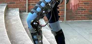
Body-conforming thigh and shin shells, F/T sensor foot platforms, and pilot device quantities without tooling investment for lower-extremity exoskeleton clinical evaluation programs.

Prosthetics Mechanism
Ti-6Al-4V and 7075-T6 hip knee ankle parts for powered prosthetic leg mechanisms — biocompatible materials, fatigue-rated structural geometry, and ISO 13485-compatible documentation.

Research Institutions
Single-robot bilateral leg component kits with complete fatigue geometry and mass documentation for university and national laboratory humanoid locomotion research.
Humanoid Robot Leg Component
Process & Capabilities
CNCPioneer's leg component process takes hip knee ankle parts from gait-loading specification through PPAP-qualified volume production — 24-hour DFM review, prototype bilateral kit delivery (18–30 days), fatigue and kinematic verification, and production qualification.
Gait-Loading DFM Review (24 Hours)
Structural adequacy under heel-strike impact and single-limb stance · Fatigue life calculation at every stress concentration · Kinematic tolerance stack from hip to foot · Mass vs. target per component with material recommendation.
Prototype Bilateral Leg Kit (18–30 Days)
Knee pivot brackets 5–7 days; hip cluster housings and ankle differential housings (5-axis) 9–14 days; complete single-leg kit 18–25 days; complete bilateral pair with symmetry verification 22–30 days.
Fatigue & Kinematic Verification
Optical comparator fillet radius verification on every fatigue-critical component · Mitutoyo CMM on all kinematic interface positions and bore angular relationships · Bilateral pairs verified for center distance and mass differential.
Production & Statistical Control
PPAP Level 3 qualification with Cpk ≥1.67 on hip fork bore coaxiality, knee bracket center distance, and F/T sensor flatness · Up to 72% per-unit reduction at 1,000+ unit volume · 2–3 week monthly blanket releases.
Leg Component Materials
7075-T6 (65% of programs) · 6061-T6 · AZ91D magnesium · Ti-6Al-4V · 17-4PH H900 · 42CrMo4 · GCr15 bearing steel · PEEK — all sourced with full mill certificates and SII XRF composition verification.
IATF 16949 / AS9100D Documentation
CoC per component, CMM reports, fillet radius verification records, bilateral symmetry differential records, mass balance records, material certifications, PPAP Level 3 for volume programs, FAIR per AS9102 for defense programs.
Materials for Humanoid
Robot Leg Components
Leg component material selection is governed primarily by fatigue endurance limit at gait-cycle stress amplitudes, not just yield strength — the property that determines whether a component survives 10⁷ loading cycles or fails in the field within two years. 7075-T6 is adequate for most standard programs; titanium becomes necessary above 250 Nm hip abduction moment.
7075-T6
2.80 g/cm³ · 572 MPa UTS · σ_endurance ≈160 MPa · Standard hip forks, knee brackets, and shin tubes — roughly 65% of humanoid leg component programs, providing 1.33× fatigue safety factor at 10⁷ cycles for standard torque classes
6061-T6
2.70 g/cm³ · 310 MPa UTS · σ_endurance ≈96 MPa · Covers, sensor mounts, and low-stress brackets outside the primary load path where machinability and cost outweigh fatigue margin requirements
AZ91D
1.81 g/cm³ · 230 MPa UTS · σ_endurance ≈70 MPa · Distal shin shells, foot panels, and lightweight thigh covers where minimum swing inertia matters more than maximum load-path fatigue margin
Ti-6Al-4V
4.43 g/cm³ · 950 MPa UTS · σ_endurance ≈500 MPa (3.1× 7075-T6) · High-load hip forks, ankle housings, and heel impact structures on programs where rated hip abduction moment exceeds 250 Nm
17-4PH H900
7.75 g/cm³ · 1,310 MPa UTS · σ_endurance ≈620 MPa · Output shafts, hip flanges, and high-stress pin seats at the small-footprint interfaces where maximum stiffness-to-weight governs
42CrMo4
7.85 g/cm³ · 1,000 MPa UTS · σ_endurance ≈450 MPa · Knee actuator shaft inserts and high-torque structural inserts at the leg's highest single-axis torque interfaces
GCr15
7.80 g/cm³ · HRC 62–65 · Pivot pin seats and knee bearing surfaces subject to sustained rolling contact load across millions of gait cycles
PEEK
1.32 g/cm³ · 100 MPa UTS · Cable guide brackets and isolation spacers within the leg where electrical isolation and low-friction cable contact outweigh structural load-bearing requirements
Surface Treatments for
Hip Knee Ankle Parts
Leg component surface treatment selection is governed by fatigue impact at load-path surfaces as much as corrosion or cosmetics — several treatments actively change the fatigue safety factor at fillet-critical locations, for better or worse if not coordinated with the underlying geometry.
Type III Hard Anodize — MIL-A-8625
Standard for aluminum leg structural components — HV 400+ protects pivot bore surfaces from scuffing. Introduces compressive residual stress (−150 to −250 MPa) that can improve fatigue life at anodized surfaces, but anodize cracks initiate at stress concentrations above the parent material endurance limit — another reason fillet compliance precedes treatment.
Electroless Nickel — MIL-C-26074
Mandatory corrosion protection for AZ91D magnesium shin shells, thigh covers, and foot panels. Plating allowance incorporated in machined feature dimensions; post-plate dimensions within ±0.003mm of target.
Passivation — ASTM A967
Mandatory for 17-4PH H900 output flanges and stainless hip knee ankle parts inserts — restoring the passive chromium oxide layer for maximum corrosion resistance without dimensional allowance.
Powder Coat
Cosmetic color and corrosion protection for shin and thigh shell panels in commercial humanoid robot programs — color-matched per OEM specification across production batches.
Shot Peening
Compressive residual stress induction (Almen A 0.15–0.25mm) at hip fork arm roots, knee bracket bore shoulders, and ankle housing boss roots — increases σ_endurance 15–30% at the peened surface, converting a 1.33× fatigue safety factor to 1.55–1.73× where geometry and finish alone leave inadequate margin.
DLC Coating — 1–3μm
Ultra-low friction (μ 0.05–0.15) for knee and ankle pivot pin running surfaces — extending pivot pin service life to 10⁷+ articulation cycles at gait-cycle loads.
All hip knee ankle parts surface treatments — hard anodize, electroless nickel, passivation, powder coat, shot peening, and DLC — are applied with dimensional and fatigue impact coordinated against the underlying geometry. Treatment certifications, including Almen strip records for shot-peened lots, are included in the shipment documentation package for every program.
IATF 16949 / AS9100D Quality System
for Humanoid Robot Leg Components
A leg component that passes first-article dimensional inspection but carries an undersized fillet at a load-path fillet root can still fail in the field within two years. CNCPioneer's quality system is built around gait-cycle loading, not just static dimensional conformance.
Gait-Loading DFM Review
Structural adequacy under heel-strike impact and single-limb stance, fatigue life at all stress concentration locations, and kinematic tolerance stack from hip to foot — reviewed before any machining commitment.
Fatigue Geometry Verification
Every load-path fillet radius on fatigue-critical components verified by optical comparator or CMM scan — hip fork root fillets, knee bracket bore shoulders, ankle housing boss roots. Out-of-spec fillet triggers rejection before surface treatment.
Material Incoming Inspection
SII XRF composition verification on every lot — 7075-T6, AZ91D, Ti-6Al-4V, 17-4PH H900. Hardness verification on 17-4PH programs. Full material certificate-to-robot-serial-number lot traceability.
Bilateral Symmetry Verification
Left/right component pairs CMM-measured for kinematic dimension differential, precision-balanced for mass differential, and paired as matched bilateral sets with differential records in shipment documentation.
Final Inspection
Mitutoyo CMM (±0.001mm): kinematic interfaces, bore diameters, angular relationships, F/T sensor flatness. Optical comparator: fillet radii. Ultrasonic wall mapping: shin tubes and thin-wall shells. Precision balance: mass and bilateral differential.
Documentation
CoC per component, CMM reports, fillet radius verification records, bilateral symmetry differential records, mass balance records, material certifications, PPAP Level 3 for volume programs, FAIR per AS9102 for defense programs.
IATF 16949 / AS9100D Quality System
Details
CNCPioneer's IATF 16949 and AS9100D certified humanoid robot leg components factory confirms independent audit compliance with the quality framework demanded by humanoid robot OEMs and legged robot developers alike.
Fatigue Geometry Documentation
Fillet radius verification records archived per component lot for every load-path fillet on fatigue-critical parts — the dimensional evidence that the designed fatigue safety factor is achieved in every component delivered, not just the one measured at first article.
- 100% fillet verification, fatigue-critical parts
- Optical comparator records
- Archived per component lot
Bilateral Symmetry Verification
Left/right leg component pairs CMM-verified for kinematic dimension differential and precision-balanced for mass differential — shipped as matched sets with documented symmetry records for whole-body controller initialization.
- Center distance differential ≤0.005mm
- Mass differential ≤0.5g
- Differential records per pair
Material Traceability & Cpk ≥ 1.67
Full material traceability from mill certificate heat number through finished component shipment. PPAP Level 3 qualification with Cpk ≥1.67 on hip fork bore coaxiality, knee bracket center distance, and F/T sensor flatness for volume programs.
- XRF alloy verification every order
- Cpk ≥ 1.67 on key characteristics
- PPAP Level 3 for volume programs
PPAP Level 3 & Volume Supply Chain Qualification
PPAP Level 3 qualification for robot actuator OEM supply chains: design records, process flow (including single-setup sequence documentation), PFMEA (covering tool wear diameter drift, rechucking elimination, thin-wall distortion failure modes).
- PPAP Level 3 for robot actuator OEM supply
- Cpk ≥ 1.67 on journal dia / bore / concentricity
- MSA Gage R&R on laser mic + air gauge
Humanoid Robot Leg Components FAQ
Common questions from humanoid robot OEMs, legged robot developers, and research institutions about CNCPioneer's gait-loading engineering, fatigue fillet verification, and bilateral symmetry program.
Four distinct phases, each stressing different components. Heel-strike (0–2% of the cycle) is the highest instantaneous load event — peak vertical ground reaction force of 1.3–1.8× body weight over just 10–20ms, transmitted through ankle, shin, and knee to the hip, plus 40–80 Nm dorsiflexion moment at the ankle. Single-limb stance (10–50%) is the longest phase — hip joint carries 0.8–1.0× body weight sustained, with a 100–250 Nm abduction moment across the hip fork, the highest continuous moment in the leg. Push-off (50–65%) generates 80–200 Nm ankle plantarflexion torque, the highest single-joint torque in the gait cycle. Swing phase (65–100%) carries no ground reaction but imposes inertial hip and knee torques from rapid leg velocity reversal, twice per cycle. CNCPioneer's DFM review runs all four phases against each component's geometry before machining.
Fillet radius is the single geometric parameter with the highest leverage on fatigue life, yet it's the parameter most often left as a drawing note rather than a primary inspection characteristic. At a hip fork arm shoulder step of 8mm under 200 Nm abduction moment, a R1.0mm fillet produces stress concentration Kt≈3.7 and alternating stress ≈185 MPa in 7075-T6 — above the ≈160 MPa endurance limit, meaning fatigue failure below 10⁷ cycles (roughly 3×10⁶). Increasing to R3.0mm drops Kt to ≈2.3 and stress to ≈115 MPa — below the endurance limit, effectively unlimited fatigue life at this loading. A fillet machined 1.0mm undersized (R2.0mm against an R3.0mm design) still passes a casual visual check but drops fatigue life to roughly 2×10⁷ cycles — borderline for a 5-year target. CNCPioneer verifies every fatigue-critical fillet to ±0.05mm by optical comparator so the designed safety factor is what actually ships.
Three measurable effects. Lateral walking deviation: a 0.010mm knee bracket center distance asymmetry between left and right legs produces different effective shin lengths, so identical joint trajectories place the two feet at different forward positions each step — over 1,000 steps that compounds to roughly 10mm of lateral path deviation, costing 3–5% walking efficiency in correction. Bilateral torque asymmetry: a 10g mass difference between left and right shin tubes shifts the two legs' swing pendulum frequency by about 0.15%, forcing asymmetric hip torques for symmetric step timing. Bilateral stance compliance asymmetry: F/T sensor platform flatness differential between feet produces different measured ground reaction forces for identical actual contact, so the balance controller responds asymmetrically to a symmetric stance — manifesting as lateral body sway. CNCPioneer's bilateral program holds center distance differential to ≤0.005mm, mass differential to ≤0.5g, and F/T flatness differential to ≤0.003mm between matched pairs.
Four recurring modes. Hip fork arm fatigue cracking at the root fillet, from a fillet machined below spec, or correctly machined but undersized by the original gait-loading analysis — prevented by DFM-specified minimum radius plus ±0.05mm optical comparator verification, with shot peening as an optional upgrade. Shin tube buckling at the knee end under heel-strike, from wall thinner than designed or an internal stress concentration in the primary load zone — prevented by minimum-wall DFM specification, in-process ultrasonic verification, and a design rule against machined features within 30mm of knee and ankle end faces. Ankle housing boss fracture at the heel-strike load entry point — prevented by fillet specification and verification at the boss root, minimum 5mm wall, and a Ti-6Al-4V upgrade path for highest-payload programs. Foot sole frame fatigue cracking at the forefoot bend zone under repeated push-off loading — prevented by fillet specification, Ra 0.8μm surface finish, and minimum-wall verification at the transition. All four are addressed in CNCPioneer's standard DFM review, not discovered after field deployment.
7075-T6 aluminum (σ_endurance ≈160 MPa) is adequate for most standard humanoid leg programs at commercial walking rates — designed hip fork geometry keeps bending stress below 120 MPa, a 1.33× safety factor at 10⁷ cycles. Titanium Ti-6Al-4V (σ_endurance ≈500 MPa, 3.1× higher) becomes necessary once rated hip abduction moment exceeds roughly 250 Nm, since that pushes 7075-T6 fork arm stress above 130 MPa and erodes the fatigue margin below target. AZ91D magnesium trades fatigue margin (σ_endurance ≈70 MPa) for the lowest density available, appropriate for distal shin shells and foot panels where swing inertia matters more than load-path margin. 17-4PH H900 and 42CrMo4 handle small-footprint, high-stress interfaces like output flanges and actuator shaft inserts where stiffness-to-weight at a compact cross-section is the driver. CNCPioneer's DFM review runs the fatigue calculation per component rather than defaulting to one material across the whole leg.
Prototype: knee pivot bracket 5–7 business days; hip 3-DOF cluster housing (5-axis) 10–14 days; ankle 2-DOF differential housing (5-axis compound bore) 9–14 days; foot sole frame with F/T sensor platform 5–7 days; complete single-leg kit 18–25 days; complete bilateral kit with symmetry verification 22–30 days. Pilot production (25–100 bilateral sets) runs 5–7 weeks per batch including symmetry pairing; PPAP Level 3 qualification takes 6–8 weeks from pilot data completeness. Volume production ships on 2–3 week monthly blanket releases — annual capacity runs 50,000+ bilateral sets for 5-axis hip/ankle programs and 200,000+ for knee bracket and shin tube programs. At representative scale, a knee pivot bracket costing $145 at US prototype pricing runs $85 at CNCPioneer prototype and $32–38 at 5,000-unit annual bilateral volume — across a leg's 50–80 unique part numbers, savings of roughly $2,000–$4,500 per bilateral set versus US domestic sourcing.
Get a Quote for Humanoid Robot Leg Components
Upload your humanoid robot leg component drawings, assembly models, or leg BOM and receive a free gait-loading DFM review and competitive quotation within 24 hours — covering heel-strike structural adequacy, fatigue life at fillet-critical locations, kinematic tolerance stack from hip to foot, bilateral symmetry specification, and complete pricing from prototype through volume production.