
Custom Large Diameter
Flange Fabrication
CNCPioneer is an IATF 16949 and AS9100D certified China large diameter flange manufacturers facility delivering custom large diameter flanges from Ø600mm through Ø6,000mm outer diameter — custom onshore wind power flange L-flange and T-flange tower ring programs, heavy industrial flanges for pressure vessels and heat exchangers, large bore ASME B16.47 weld neck and blind flanges, turbine casing flanges, compressor frame flanges, large process column base ring flanges, offshore jacket pile top flanges, and reactor vessel nozzle flanges — with machined face flatness 0.020mm/1,000mm, bore accuracy ±0.050mm, bolt circle true position ±0.020mm, and Ra 3.2–6.3μm sealing face finish directly from VTC turning, with 100% CMM documentation per flange.
Vertical turning centers (VTC) to Ø2,500mm, horizontal boring mills to Ø4,000mm effective, and qualified ring rolling and forging supply-and-machine programs to Ø6,000mm — serving wind turbine tower manufacturers, heavy pressure vessel fabricators, power generation equipment builders, offshore structure constructors, large pump and compressor manufacturers, steel mill equipment producers, and mining equipment OEMs since 2011.

What Is Custom Large
Diameter Flange Fabrication?
Custom large diameter flange fabrication is the integrated supply chain process — encompassing ring rolling, forging, plate flame cutting, and precision CNC vertical turning and boring mill machining — by which structural and pressure-containing flange components above Ø600mm outer diameter are produced to application-specific dimensional, material, and certification specifications that catalog supply cannot satisfy.
Large diameter flanges occupy a distinct engineering and manufacturing category from standard pipe flanges for three reasons. First, starting material form: flanges above Ø600mm are produced from ring-rolled or forged ring blanks whose continuous circumferential grain flow provides the hoop stress resistance, fatigue performance, and impact toughness that heavy industrial and wind power flange structural requirements demand. Second, machine platform: large diameter flanges require vertical turning centers (VTCs) with Ø1,000–3,000mm table capacity or horizontal boring mills — capital equipment that concentrates capability among qualified China large diameter flange manufacturers. Third, dimensional verification at scale: confirming 0.020mm/1,000mm face flatness on a Ø2,000mm wind power tower flange requires CMM capability with 3,000mm working volume that separates qualified programs from general fabrication facilities.
-
VTC machining to Ø2,500mm enabling face flatness 0.020mm/1,000mm CNCPioneer's vertical turning centers accommodate ring forgings to 15,000kg; in-process adaptive facing protocol with CNC contact probe corrects any flatness deviation exceeding 0.015mm during the facing operation itself — not only at final CMM measurement.
-
Custom ring forging for wind power flange supply chain integration Ring rolling procurement, incoming UT verification, precision VTC machining, coordinated MT, CMM dimensional report, and hot-dip galvanize — all under one lot number and one EN 10204 3.1 or 3.2 certificate. Eliminates the five-subcontractor coordination burden of standard large diameter flange procurement.
-
IEC 61400-6 and GL Guidelines dimensional discipline in routine production Wind power tower flange programs achieve face flatness 0.020mm/1,000mm, cross-face parallelism 0.030mm, and bolt circle true position ±0.020mm as routine production specification on every flange — verified by 37-point 3D CMM per piece — not as exceptional first-article performance.
-
40 to 60 percent cost advantage versus European large diameter flange suppliers CNCPioneer delivers 40–60% below German, Dutch, and Spanish ring-rolling and machining facilities at equivalent dimensional accuracy, material certification, and NDT documentation. At 1,500 annual wind power flanges, this generates $480,000–$870,000 annual procurement cost reduction for tower manufacturers.

Why CNCPioneer for
Custom Large Diameter Flange Fabrication?
Among China large diameter flange manufacturers, CNCPioneer's vertical turning center capacity to Ø2,500mm, integrated ring forging supply chain, IEC 61400-6 and GL Guidelines dimensional discipline in routine production, heavy industrial flange engineering review as standard DFM scope, 40–60% cost advantage versus European alternatives, and single-source supply from ring forging through NDT and coating establish our facility as the preferred large diameter flange in China partner for wind turbine tower OEMs, pressure vessel fabricators, and heavy industry equipment builders globally.
Vertical Turning Center Machining to Ø2,500mm
Precision large diameter flange machining requires vertical turning centers (VTCs) whose rotating table holds the flange horizontally while turning tools engage from above — the machine configuration that allows large, heavy ring forgings (500kg–15,000kg) to be placed, chucked, and machined without the workpiece deflection that horizontal turning would impose on large-diameter thin-ring components. CNCPioneer's VTC capacity extends to Ø2,500mm table diameter, accommodating tower flanges from wind power programs to 2MW+ turbine class and large pressure vessel nozzle flanges in single-setup programs machining all critical faces from one vertical turning reference datum — achieving face flatness 0.020mm/1,000mm, bore ±0.050mm, and bolt circle ±0.020mm.
Custom Ring Forging for Wind Power Flange Supply Chain Integration
CNCPioneer's custom ring forging for wind power flange programs integrate the complete supply chain: ring rolling of S355J2+N, S355NL, Q345E, or 42CrMo4 forged ring blanks at qualified Chinese ring rolling mills with EN 10204 3.1 or 3.2 certification; incoming ring dimensional and material verification at CNCPioneer; 100% UT per EN 10228-3 Class 3 record review; precision VTC machining to finished flange dimensions; and CMM dimensional report with material certificate documentation — all under one lot number and one Certificate of Conformance. This eliminates the multi-subcontractor coordination burden where ring rolling, heat treatment, NDT, and machining are managed as separate purchase orders with separate accountability gaps.
IEC 61400-6 Dimensional Discipline at Production Scale
Wind power tower flanges are simultaneously the highest-volume large diameter flange application and the one with the tightest dimensional requirements relative to flange size. IEC 61400-6 and GL Guidelines tower structural specifications require: L-flange and T-flange mating face flatness 0.020mm/1,000mm for bolt joint pre-load compliance; bolt circle true position ±0.020mm for simultaneous engagement of 80–140 tower bolts; and cross-flange parallelism 0.030mm to prevent induced bending stress at the bolted joint. CNCPioneer achieves these specifications in routine production — with 100% 37-point 3D CMM flatness verification on every wind power tower flange before shipment — not as exceptional first-article performance.
Heavy Industrial Flange Engineering Review as Standard DFM Scope
Every heavy industrial flange inquiry at CNCPioneer receives engineering review covering: material grade selection for operating temperature, pressure class, and corrosion environment; ring forging vs. plate fabrication recommendation for the specific OD and application loading; minimum flange web thickness from pressure rating and structural loading analysis; bolt circle design for simultaneous engagement; sealing face specification per gasket type; and heat treatment specification for alloy steel flanges where PWHT affects final dimensional compliance. This engineering depth positions CNCPioneer as a large diameter flange manufacturing partner rather than a drawing-to-part production shop receiving completed designs.
Large Diameter Flange in China — 40–60% Cost Advantage
CNCPioneer as a China large diameter flange manufacturers facility delivers 40–60% below equivalent large diameter flange fabrication from European (German, Dutch, Italian) and North American heavy flange producers at equivalent dimensional accuracy, material certification, and NDT documentation. For a standard S355J2+N L-flange Ø1,500mm hot-dip galvanized with CMM and EN 10204 3.1, CNCPioneer China large diameter flange manufacturers pricing runs $580–$720 per flange versus $950–$1,300 per flange from European suppliers — a $320–$580 per-unit saving that generates $480,000–$870,000 annual cost reduction at 1,500 flanges per year.
Single Source from Ring Forging Through NDT and Coating
CNCPioneer coordinates the complete large diameter flange fabrication supply chain: ring rolling procurement at qualified Chinese forging mills; heat treatment at qualified facilities; precision VTC and boring mill machining; UT (EN 10228-3) and MT (EN 10228-1) at qualified NDT subcontractors; and surface treatment (hot-dip galvanize ISO 1461, thermal spray zinc EN ISO 2063, epoxy duplex coating system) — delivering large diameter flanges as finished, documented components ready for direct incorporation into tower, vessel, or machine assembly with one complete documentation package per serial number.
Custom Large Diameter Flange
Types We Fabricate
CNCPioneer's custom large diameter flange fabrication covers the complete range from wind power tower L-flanges and T-flanges through ASME B16.47 large bore pressure vessel nozzle flanges, turbine casing split flanges, compressor frame flanges, column base ring flanges, offshore monopile top flanges, and reactor vessel nozzle flanges — all from Ø600mm through Ø6,000mm OD with EN 10204 3.1 or 3.2 material certification, UT and MT NDT, and 100% CMM dimensional verification.

L-Flange — Onshore Wind Power Tower Section
The standard custom onshore wind power tower section flange — L-shaped cross-section with vertical leg welded to tower shell and horizontal flange leg providing the bolted mating face between tower sections. OD range Ø1,000–Ø3,500mm per tower class. Mating face flatness 0.020mm/1,000mm for pre-load compliance across all 80–140 tower bolts. Cross-flange parallelism (top face to bottom face) 0.030mm to prevent induced bending moment. Bolt hole circle true position ±0.020mm for simultaneous bolt engagement. Surface Ra 6.3μm standard; Ra 3.2μm for Tension Control Bolt (TCB) high-friction programs. Material: S355J2+N (EN 10025-2) standard; S355NL for cold climate; Q345E for China domestic programs; 42CrMo4+QT for high-strength mass-reduction programs. 100% CMM per flange; 100% UT EN 10228-3 Class 3; hot-dip galvanize ISO 1461. IEC 61400-6 and GL Guidelines documentation standard.

T-Flange — Tower Base and Nacelle Connection
The T-flange has a symmetric T cross-section — a central web with two mating faces on both outer legs — required at tower-to-nacelle connections (top tower section) and tower-to-foundation connections (base ring T-flange at concrete foundation anchor bolt circle). Dual mating face configuration: both outer faces simultaneously flat (0.020mm/1,000mm) and parallel (0.030mm) to each other and perpendicular to the T-web axis. Dual bolt circle: bolts engaging through both flange legs require coincident bolt circles in both legs within ±0.020mm. CNCPioneer's VTC programs machine T-flanges in two sequential operations — face A then part inversion for face B — with CMM cross-face parallelism verification before final facing pass to confirm 0.020mm specification is achieved before finish pass correction. More complex machining than L-flange; 2–3 day additional VTC time per piece at equivalent size.

Foundation Base Ring — Tower Base and Monopile
The largest diameter custom large diameter flange element — the annular base ring welded to the tower bottom section and connected to concrete foundation anchor bolts for onshore programs. OD range Ø2,000mm–Ø5,000mm for modern 4–6MW onshore wind turbines. Material: S355J2+N or S355NL plate or ring forging; thickness 60–150mm. Anchor bolt circle 80–160 M36–M52 anchor bolts at ±0.020mm true position. Grout contact face (bottom) flatness 0.050mm/2,000mm for correct grout distribution at foundation interface. CNCPioneer: Ø2,000–Ø2,500mm base rings on VTC; Ø2,500–Ø5,000mm base rings on horizontal boring mill with precision rotary table. Offshore monopile top flanges to Ø6,000mm in S355G10+M or S460G1+M with thermal spray zinc or duplex epoxy coating for seawater immersion and splash zone service. EN 10204 3.2 with independent inspector for offshore DNV/GL programs.

ASME B16.47 Large Bore Pressure Vessel Nozzle Flanges
Large bore nozzle flanges for chemical reactors, distillation columns, heat exchangers, and storage vessels per ASME B16.47 Series A (MSS SP-44) and Series B (API 605). Size range NPS 26 through NPS 60 (Ø660mm through Ø1,524mm bore) in Class 150, 300, 600, 900, and 1500. Types: weld neck, slip-on, and blind per ASME B16.47 dimensional tables. CNCPioneer VTC capability: NPS 26–NPS 48 on VTC Ø2,500mm table; NPS 48–NPS 60 requiring Ø1,500mm+ bore on horizontal boring mill. Bore ±0.050mm; hub taper ±0.5 degrees per ASME B16.25 weld end compliance; raised face height ±0.050mm; sealing face Ra 3.2–6.3μm spiral. EN 1092-1 DN 650–DN 2000 in PN 6–PN 400 also produced from same VTC programs. Materials: ASTM A105, A182 F304L/F316L, A182 F22, A182 F91, A182 F51 duplex, B564 N06625. EN 10204 3.1 or 3.2 material certification; NACE MR0175 hardness compliance on applicable grades.

Steam Turbine Casing and Compressor Frame Flanges
Horizontal split plane flanges for large steam turbine casings — the precision mating faces along which upper and lower turbine casing halves bolt together. Face flatness 0.010mm/1,000mm (tighter than standard large industrial flanges) for metal-to-metal steam sealing at the split plane. Bolt circle true position ±0.015mm for simultaneous 120–280 bolt engagement at turbine casing assembly. Material: alloy steel 1.25Cr-0.5Mo or 2.25Cr-1Mo for steam to 565 degrees C; high-alloy 9–12% Cr for ultra-supercritical steam. Non-circular casing flanges require horizontal boring mill or large-table 5-axis face milling (MAZAK VARIAXIS) — CNCPioneer achieves 0.010mm/1,000mm flatness on non-circular casing flanges by precision face milling with thermal compensation during extended machining cycles. Compressor frame flanges: large bore casing flanges Ø800–Ø2,500mm at 0.015mm/1,000mm for metal-to-metal split line sealing; reciprocating compressor cylinder flanges Ø500–Ø1,200mm with bore matched to piston diameter ±0.050mm for cylinder liner installation. UT and MT (DIN 1690) pre-machining; LPT on finished faces.

Column Base Ring, Reactor, Offshore & Specialty Flanges
Large bore reactor and column base ring flanges: heavy annular structural flanges anchoring tall distillation columns and reactors to foundation skirts — OD Ø1,200–Ø5,000mm; anchor bolt circle 24–80 bolts at ±0.020mm true position; grout contact face flatness 0.050mm/3,000mm for correct foundation load distribution; skirt weld prep on OD or ID; weight 500kg–15,000kg. Materials: ASTM A105 or A36 for ambient temperature vessels; A182 F11/F22 for elevated temperature reactors. Offshore jacket pile top flanges: annular flanges for offshore wind and oil and gas jacket structure piles — OD Ø3,000–Ø6,000mm in S355G10+M or S460G1+M; 100% UT EN 10228-3 Class 3; MT EN 10228-1 Class 2; duplex coating system (primer + epoxy + antifouling) for splash zone. Mining and steel mill specialty flanges: large bore mill feed and discharge flanges in wear-resistant grades; rolling mill spindle coupling flanges in 42CrMo4; converter tilt drive flanges with fatigue geometry and impact test documentation; crane boom root flanges in 34CrNiMo6.
Industries and Applications
CNCPioneer's China large diameter flange manufacturers programs serve every industry requiring large diameter flange fabrication above Ø600mm OD — from wind turbine tower OEMs needing 50,000+ annual custom onshore wind power flanges with IEC 61400-6 documentation through power generation equipment builders requiring F91 alloy steel nozzle flanges at face flatness 0.010mm/1,000mm for supercritical steam service.

Onshore Wind Power
Custom onshore wind power flange OEM supply for tower manufacturers producing 2–6MW turbine towers — L-flange and T-flange in S355J2+N, S355NL, and Q345E from ring rolling plus VTC machining; flatness 0.020mm/1,000mm; bolt circle ±0.020mm; 100% CMM per piece; hot-dip galvanize per ISO 1461; complete GL and IEC 61400-6 documentation. Blanket order with dedicated VTC capacity, pre-purchased ring forging inventory in standard sizes, and 6-week safety stock for production schedule continuity. Volume tiers from 20 to 500+ tower sets annually with pricing minus 30–65% below prototype at volume.
Offshore Wind Power
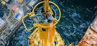
Custom ring forging for wind power flange programs for monopile and jacket foundation flanges in S355G10+M and S460 offshore structural grades — Ø3,000–Ø6,000mm offshore monopile top flanges; EN 10204 3.2 material certification with independent inspector co-signature; 100% UT EN 10228-3 Class 3; MT EN 10228-1 Class 2; DNV-GL and Bureau Veritas classification society documentation; thermal spray zinc (150μm ZnAl) or duplex epoxy coating system (Sa 2.5 blast + Zn-rich primer + high-build epoxy + antifouling topcoat, total DFT 285–380μm) per offshore corrosion protection specification.

Oil and Gas — Refinery and Petrochemical
Large bore ASME B16.47 Series A and Series B flanges NPS 26 through NPS 60 in A105, A182 F22, F91, F51 duplex, and F53 super duplex — EN 10204 3.1 or 3.2 material certification; NACE MR0175 hardness compliance; passivated stainless flanges; complete CMM dimensional report per ASME B16.47 dimensional compliance verification. Large bore column base ring flanges for distillation column and reactor foundation skirts in A105 and A36 with anchor bolt circle ±0.020mm and grout contact face flatness 0.050mm/3,000mm.

Power Generation
Steam turbine casing split flanges with face flatness 0.010mm/1,000mm for metal-to-metal steam sealing; large bore steam nozzle flanges in A182 F22 (to 650 degrees C) and F91 (supercritical to 650 degrees C); LP turbine exhaust flanges; boiler drum connection flanges in large bore ASME B16.47. 100% UT (EN 10228-3 Class 3) and MT (EN 10228-1 Class 2) documentation; EN 10204 3.2 for main steam flanges in utility power programs requiring independent inspection authority; horizontal boring mill programs for non-circular turbine casing flanges with thermal compensation during extended milling cycles.

Chemical and Process Plants
Large bore process vessel nozzle flanges in 316L, duplex 2205, and alloy steel per ASME B16.47 and EN 1092-1; column base ring flanges and reactor shell flanges for petrochemical and chemical plant construction; passivated or electropolished stainless flanges for process purity per EHEDG and pharmaceutical standards; large bore orifice flanges for process metering programs. Complete documentation per project piping material specification (PMS) and piping material requisition (PMR) for EPC contractor supply chain programs covering multiple simultaneous flange standards and grades in one project delivery.

Mining, Steel Mill & Shipbuilding
Mining and minerals processing: large bore mill feed and discharge flanges in wear-resistant grades; slurry pump casing flanges with modified sealing face geometry for slurry-resistant gasket systems; thickener drive flanges with oversized bore for rubber liner installation. Steel mill equipment: rolling mill spindle coupling flanges in 42CrMo4 with fatigue-rated geometry; converter tilt drive flanges with impact test documentation; ladle lifting lug flanges with stress calculation. Shipbuilding and marine machinery: large propulsion system flanges and azimuth thruster frame flanges with DNV, ABS, Lloyd's Register, and Bureau Veritas classification society documentation and marine-grade corrosion protection systems.
Large Diameter Flange Fabrication
Process and Capabilities
CNCPioneer's large diameter flange fabrication runs on vertical turning centers (VTC) to Ø2,500mm table for standard programs; horizontal boring mills to Ø4,000mm effective for above-VTC-capacity and non-circular flanges; large-table MAZAK VARIAXIS 5-axis for complex casing and structural flanges; and qualified ring rolling supply-and-machine programs sourcing ring forgings from Ø600mm to Ø6,000mm at qualified Chinese forging mills with EN 10204 3.1 or 3.2 certification.
24-Hour Engineering DFM and Flange Configuration Review
Material grade selection for operating temperature, pressure class, and corrosion environment. Ring forging vs. plate fabrication recommendation for the specific OD and application loading — plate economical for Ø600–Ø1,000mm one-offs; ring forging required for wind power and fatigue-rated structural programs above Ø800mm. Minimum flange web thickness from pressure rating and structural loading analysis. Bolt circle design for simultaneous engagement of all bolt holes. Sealing face specification per gasket type (Ra 6.3μm for standard metal-to-metal; Ra 3.2μm for high-friction TCB programs; Ra 1.6μm for elastomeric gasket). Heat treatment specification for alloy steel (F22, F91, 42CrMo4) where PWHT affects final dimensional compliance and requires post-heat-treatment machining stock planning. EN 10204 3.1 or 3.2 routing per regulatory requirement. UT and MT class specification per service. Surface treatment specification. Complete pricing from first-article prototype through OEM blanket supply.
Vertical Turning Center — Ø600mm–Ø2,500mm Table
CNCPioneer's VTC programs accommodate ring forgings to 15,000kg on precision rotary table; boring bar reach 1,200mm axial for deep bore features in tall ring flanges; facing diameter full Ø2,500mm radial pass in one C-axis revolution. VTC process sequence: ring blank mounting by overhead crane with 4-point contact check; rough facing and boring; minimum 4-hour thermal stabilization protocol before finish operations (eliminating ±15 degrees C temperature gradient producing ±0.9mm diameter variation on Ø1,500mm ID); finish facing with CNC contact probe in-process adaptive correction; air gauge bore verification at 0.1mm resolution; C-axis bolt hole drilling (all holes in one indexed program from bore datum without table repositioning); part inversion and second face machining with CMM cross-face parallelism verification before final pass. Achieves face flatness 0.020mm/1,000mm, bore ±0.050mm, bolt circle ±0.020mm, cross-face parallelism 0.030mm as routine production specification.
Horizontal Boring Mill — Ø2,500mm to Ø6,000mm and Non-Circular
For large diameter flanges above VTC table capacity (Ø2,500mm+) and for non-circular heavy industrial flanges (turbine casing flanges, compressor frame flanges), CNCPioneer's horizontal boring mill programs achieve: precision rotary table to Ø4,000mm effective diameter; boring bar to Ø3,000mm bore diameter with supported anti-deflection tooling; face milling to 3,000mm x 3,000mm table travel; angular positioning ±0.005 degrees for bolt circle drilling on rotary table. Non-circular turbine casing flanges require face milling (200mm face mill, 0.080mm pass depth, 400 RPM for controlled thermal input) producing face flatness 0.010mm/1,000mm on non-circular geometries. Foundation base rings Ø2,500–Ø5,000mm and offshore monopile flanges Ø3,000–Ø6,000mm machined in horizontal boring mill programs with full CMM 37-point verification on Renishaw scanning probe system with 3,000mm working volume.
Ring Forging Supply-and-Machine Programs
CNCPioneer's ring rolling procurement program sources qualified ring-rolled blanks from established Chinese ring rolling mills meeting: ISO 9001 or IATF 16949 certification; EN 10228-3 UT capability (100% volumetric UT); heat treatment furnace with temperature uniformity ±15 degrees C and furnace chart recording per EN 10204 3.1 requirements; mechanical test laboratory with tensile, CVN impact, and hardness testing per ISO/IEC 17025 accreditation; and EN 10204 3.1 (standard) or 3.2 (with third-party witness) certification issuance capability. CNCPioneer maintains pre-purchased ring forging inventory in the most common S355J2+N wind power flange sizes (Ø1,200mm, Ø1,500mm, Ø2,000mm, Ø2,500mm) — reducing prototype lead time for these standard sizes to 8–12 business days from ring forging through CMM-verified machined deliverable. Incoming inspection at CNCPioneer: SII XRF composition check against EN 10204 3.1 mill certificate; Brinell hardness 3+ positions; dimensional incoming (OD, ID, height) confirming machining stock adequacy; UT record review.
UT and MT Non-Destructive Testing Programs
UT (Ultrasonic Testing) per EN 10228-3: 100% volumetric UT on ring forgings for all large diameter flanges; scan coverage 100% of forging volume in at least two perpendicular directions; acceptance class EN 10228-3 Class 3 for wind power tower flanges; Class 4 for nuclear and critical pressure vessel applications; discontinuity types detected: laminations, inclusions, segregations, porosity above acceptance class equivalent reflector size. UT performed after heat treatment and rough machining before precision machining investment. Qualified UT technician per EN ISO 9712 Level 2 minimum; records archived per flange serial number. MT (Magnetic Particle Testing) per EN 10228-1: wet fluorescent MT on all machined surfaces; acceptance Class 2 for wind power programs; Class 3 for turbine casing and critical pressure vessel flanges; after finish machining before surface treatment — detecting surface discontinuities from machining, grinding, or heat treatment that would be masked by coatings. LPT (Liquid Penetrant Testing) on finished flange faces for turbine casing and precision sealing programs. All NDT certificates archived per flange serial number and shipped with delivery documentation package.
EN 10204 3.1/3.2, IEC 61400-6, GL/DNV, PPAP Level 3
EN 10204 3.1 material certificate with heat number traceability from steel mill through ring rolling through CNCPioneer machining lot to individual flange serial number — standard with every large diameter flange shipment. EN 10204 3.2 with independent third-party inspector co-signature — available with 5–7 business day additional lead time for inspector scheduling for PED 2014/68/EU, nuclear, and DNV/GL offshore structural programs. IEC 61400-6 and GL Guidelines dimensional compliance documentation for wind power tower flange programs: 37-point 3D CMM flatness report confirming 0.020mm/1,000mm; bolt circle true position report all holes simultaneously; cross-face parallelism at 12 angular positions; material CVN impact compliance; UT and MT certificates per flange serial number; hot-dip galvanize coating weight per ISO 1461; Certificate of Conformance. PPAP Level 3 Cpk documentation for custom onshore wind power flange OEM programs including Gage R&R on CMM and profilometer, initial capability studies Cpk 1.67 or above on face flatness and bolt circle, and part submission warrant. Records retained 20 years.
Materials for
Custom Large Diameter Flange Fabrication
Custom large diameter flange material selection is governed by application structural loading (yield strength, CVN impact toughness at specified test temperature), operating pressure and temperature range, corrosion environment, IEC 61400-6 or ASME/EN code requirements, and EN 10204 certification class. S355J2+N dominates onshore wind power tower flange programs; offshore grades S355G10+M and S460NL address cold climate and seawater structural requirements; A105 through F91 cover the pressure vessel and high-temperature piping range.
S355J2+N — EN 10025-2
Yield strength 355 MPa minimum; CVN impact 27J at -20 degrees C; the dominant material for standard onshore wind power tower L-flanges and T-flanges in temperate climate programs. N suffix confirms normalized delivery condition — essential for grain size uniformity and fatigue performance in ring-rolled and subsequently VTC-machined large diameter flanges. Weldability excellent: CEV approximately 0.43 for S355J2, within the range for preheat-free welding to 25mm; above 25mm preheat 75-125 degrees C per EN 1011-2 recommendation. CNCPioneer ring forging pre-purchase inventory includes standard S355J2+N sizes Ø1,200mm, Ø1,500mm, Ø2,000mm, and Ø2,500mm for prototype lead time reduction to 8–12 business days. EN 10204 3.1 standard; 3.2 with inspector witness available. Hot-dip galvanize ISO 1461 standard surface treatment.
S355NL — EN 10025-3
Yield strength 355 MPa minimum; CVN impact 27J at -50 degrees C (NL suffix = normalized, low temperature toughness sub-grade). Required for onshore wind power tower flanges in cold climate programs: Scandinavian, Canadian Prairie, Siberian, and Mongolian wind power installations where winter ambient temperature reaches -30 to -50 degrees C during turbine operation or maintenance. The NL sub-grade achieves -50 degrees C CVN compliance through controlled chemistry (reduced sulphur, controlled nitrogen) and fine-grain normalization — not simply by normalizing S355J2. EN 10204 3.1 standard; 3.2 available with additional lead time for inspector scheduling. Mill certificate must document actual CVN test results at -50 degrees C, not merely specification compliance — CNCPioneer verifies actual values against specification at incoming inspection before machining release.
S355G10+M and S460NL — EN 10025-6
S355G10+M: yield strength 390 MPa; CVN 27J at -40 degrees C; offshore sub-grade with reduced sulphur max 0.010% for through-thickness toughness (Z35 direction property) in thick-section monopile top flanges. Thermomechanical controlled process (+M suffix) delivers tighter microstructure than normalization alone for plate and ring forging. S460NL: yield strength 460 MPa minimum; CVN 27J at -50 degrees C; for weight-optimized monopile and offshore tower designs where higher yield strength reduces flange section thickness and total tower weight at equivalent structural performance. EN 10204 3.2 with independent inspector co-signature is the standard certification class for offshore structural primary components per DNVGL-ST-0126 and EN 1993-1-1 offshore structure design standards. Duplex coating system (TSZ + epoxy + antifouling) as standard surface treatment for seawater immersion and splash zone zones.
Q345E — GB/T 1591
Yield strength 345 MPa; CVN 27J at -40 degrees C; the Chinese national standard structural steel grade that is the domestic equivalent of S355NL for onshore wind power tower flange programs in China domestic market projects. Q345E is specified in Chinese wind turbine OEM tower designs produced for China Energy Investment, State Power Investment Corporation, China Southern Power Grid, and Goldwind tower manufacturing programs where project specifications reference GB/T 1591 rather than EN 10025. EN 10204 3.1 equivalent certification per Chinese inspection standard GB/T 2975; chemical and mechanical test report per heat number. Hot-dip galvanize per GB/T 13912 (equivalent to ISO 1461) standard surface treatment. CNCPioneer produces Q345E large diameter flanges from ring rolling at qualified Chinese steel mills with Chinese standard mill test certificates fully documented for domestic project acceptance.
ASTM A105 — Standard Carbon Steel
C max 0.35%; yield strength 250 MPa; Brinell max 187 HB for NACE MR0175 H2S compliance. Temperature range -29 degrees C through +425 degrees C per ASME B31.3. The default material for large bore ASME B16.47 flanges NPS 26–NPS 60 in non-corrosive hydrocarbon, steam, and utility service. Column base ring flanges, large bore process vessel nozzle flanges, and compressor cylinder flanges where alloy steel is not required by temperature or pressure class. Bar stock for NPS 26–NPS 36; plate flame cut for large base ring programs to Ø3,000mm; ring rolling for NPS 36+ weld neck flanges requiring hub grain flow continuity. XRF composition verification on every lot at CNCPioneer; Brinell hardness per lot. EN 10204 3.1 standard; NACE MR0175 hardness compliance statement available. Zinc plate ASTM B633 or hot-dip galvanize ASTM A123 as standard corrosion protection.
ASTM A182 F22 and F91 — Chrome-Moly Alloy Steel
F22 (2-1/4Cr-1Mo): to 650 degrees C; the workhorse alloy for large bore steam turbine nozzle flanges, main steam piping flanges, hydrocracker and hydrotreater large nozzle flanges. Brinell max 200 HB NACE compliance in normalized plus tempered condition. PWHT required after welding (690–750 degrees C); CNCPioneer DFM accounts for PWHT distortion in post-heat-treatment machining stock planning for large bore flanges. F91 (9Cr-1Mo-V): to 650 degrees C at substantially higher allowable stress; for supercritical and ultra-supercritical steam turbine nozzle flanges and large reactor steam outlet flanges. HB 187–248 narrow window verified incoming by Brinell per lot — delta ferrite from incorrect heat treatment produces loss of creep strength not visible by external inspection. Both grades machined from ring forgings with EN 10204 3.2 material certification as standard for utility power plant programs. UT Class 3 and MT Class 2 NDT documentation standard.
316L and ASTM A182 F316L
PREN approximately 24.3; Cr 16–18%, Ni 10–14%, Mo 2–3%; temperature range -196 through +870 degrees C. The standard material for large bore process vessel nozzle flanges in chemical, pharmaceutical, food, and offshore splash zone service. Large bore 316L flanges NPS 16–NPS 48 machined from ring forgings (bar stock impractical above NPS 16 for hub grain flow programs); NPS 26–NPS 60 per ASME B16.47 Series A or B. Passivation ASTM A967 as standard post-machining treatment. For large bore sanitary pharmaceutical vessel nozzle flanges: electropolish Ra 0.4μm on wetted bore and face surfaces; EHEDG crevice-free geometry; ISO 13485-compatible passivation documentation. EN 10204 3.1 standard; NACE MR0175 Brinell max 200 HB compliance documented per lot. VTC single-setup machining of bore, face, and hub from one datum for bore-to-face perpendicularity in large bore programs.
Duplex 2205 — ASTM A182 F51 (UNS S31803/S32205)
PREN approximately 35.4; yield strength 450 MPa minimum; CVN 27J at -46 degrees C. For large bore stainless process vessel nozzle flanges in seawater cooling systems, offshore topsides process vessels, amine treating columns, FGD absorber vessels, and desalination plant vessels. PREN 35 substantially exceeds 316L (PREN 24) for pitting resistance in high-chloride environments. Higher yield strength than austenitic stainless allows lighter flange section at equivalent pressure rating — particularly relevant for large bore (NPS 24+) programs where flange weight becomes a significant cost and handling factor. CNCPioneer: dedicated duplex machining parameters; pickling-and-passivation treatment (HNO3/HF pickle + ASTM A967 passivation) standard for duplex large bore flanges to remove surface ferrous contamination. NACE MR0175 Rockwell max 28 HRC in solution-annealed condition documented per lot. EN 10204 3.1 with PREN calculation documentation; 3.2 available for offshore PED and DNV programs.
42CrMo4+QT and 34CrNiMo6 — EN 10083-3
42CrMo4+QT: quenched and tempered; yield strength 650 MPa minimum; for high-strength wind power bolt flanges where mass reduction drives use of higher-yield material instead of standard S355; drivetrain connection flanges between wind turbine gearbox and main shaft; rolling mill spindle coupling flanges requiring fatigue-rated geometry under cyclic torsional loading; crane boom root flanges under bending fatigue with stress concentration at the boom root cross-section. 34CrNiMo6: yield strength 800 MPa minimum at appropriate section thickness; for crane boom root flanges, large machine tool spindle mounting flanges, and heavy industrial coupling flanges requiring maximum yield in the 700–900 MPa range. Both grades: QT condition incoming verification by Brinell hardness per lot; CVN impact test records from mill certificate; no heat treatment permitted after precision machining (QT condition is the specified mechanical property state for both grades). UT Class 3 and MT Class 2 NDT documentation standard for structural fatigue-rated programs.
A36 / S275 and S460G1+M — Carbon and High-Yield Structural
A36 / S275: yield strength 250 MPa; ambient temperature structural steel for column base ring flanges, process vessel skirt flanges, and equipment foundation flanges where structural loading governs without pressure-area calculation requirements from ASME VIII. Lower cost than A105 for large base ring flanges where ASME flange dimensional specification is not required (structural applications with project-specific dimensional drawings). Available in plate (for base rings flame-cut from heavy structural plate) and ring forging (for continuous grain flow in fatigue-critical base ring applications). S460G1+M: yield strength 460 MPa minimum; thermomechanically processed structural steel for high-strength monopile and offshore jacket structural flanges where higher yield reduces section thickness and total tonnage. Applied at CNCPioneer's horizontal boring mill for foundation base rings Ø2,500–Ø5,000mm; epoxy duplex coating system (Sa 2.5 blast, Zn-rich primer, high-build epoxy, polyurethane topcoat) standard surface treatment for buried and immersed structural applications.
Surface Treatments for
Custom Large Diameter Flanges
Custom large diameter flange surface treatments serve three engineering functions: long-term atmospheric corrosion protection on structural steel wind power and offshore flanges (hot-dip galvanize, thermal spray zinc, epoxy duplex coating system); passive layer restoration on stainless and duplex large bore pressure vessel nozzle flanges (passivation, pickling-and-passivation); and transit and storage protection on carbon steel heavy industrial flanges (phosphate plus rust preventive). Treatment masking of precision mating faces and bolt hole threads is incorporated into the treatment plan at DFM stage — post-galvanize VTC touch-facing restores any flatness deviation from galvanize temperature warpage to 0.020mm/1,000mm specification.
Hot-Dip Galvanize — ISO 1461 / ASTM A123 (Structural Steel Flanges)
Standard long-term external corrosion protection for S355 and Q345 wind power tower flanges and S275/A36 structural flanges — 85μm minimum average coating per ISO 1461 (average coating thickness on heavy structural pieces; actual coating thickness varies by section thickness and steel composition). Applied to the complete tower flange body exterior except precision mating faces and bolt holes which are masked before immersion in zinc bath. Post-galvanize VTC touch-facing of mating faces restores flatness to 0.020mm/1,000mm after any galvanize temperature warpage from the 440–460 degrees C zinc bath; CNCPioneer plans this VTC touch-facing step into the production flow for all wind power tower flange programs. Bolt hole threads tapped post-galvanize to restore thread form. Galvanize certificate per ISO 1461 (coating weight per piece measured by weigh-before/weigh-after method) shipped with every lot. For high-friction surface programs: galvanize applied to bolt bearing faces before mating face machining; mating face then machined to final flatness specification through galvanize layer; Ra 3.2μm finish retained on galvanized bearing face for TCB installation.
Galvanize specsThermal Spray Zinc — EN ISO 2063 (Offshore Flanges)
Arc-sprayed zinc (150μm) or zinc-aluminium alloy Zn85Al15 (150μm) coating for offshore monopile top flanges, jacket pile flanges, and offshore wind foundation structural flanges — superior cathodic protection coverage on complex geometries and internal surfaces compared to hot-dip galvanize, which has difficulty achieving uniform coverage inside large bore deep-bore flanges. Thermal spray zinc applies the zinc or ZnAl feedstock wire as atomised droplets at cold-spray temperature (150–180 degrees C) far below the 440–460 degrees C galvanize bath, eliminating thermal distortion risk on large precision flanges above Ø2,000mm where hot-dip galvanize temperature warpage on face flatness would require extensive post-galvanize re-machining. Mating face and bolt hole zones masked during thermal spray application. Compatible with duplex paint system overcoat as the cathodic protection underlayer. Applied per EN ISO 2063-1 (Zinc and Zinc Alloys) and EN ISO 2063-2 (Execution); coating weight verified by magnetic induction gauge on representative test coupons sprayed simultaneously with production flanges. TSZ certificate per flange lot shipped with delivery documentation.
TSZ specsEpoxy Duplex Coating System — Offshore and Buried Service
Project-specified coating system for offshore wind foundation flanges in continuous seawater zone, buried structural flanges, and marine splash zone applications where hot-dip galvanize or TSZ alone is insufficient for the design service life. System specification: surface preparation Sa 2.5 near-white blast per ISO 8501-1 (profile Rz 50–85μm per SSPC-SP10 for mechanical adhesion of primer); primer: zinc-rich epoxy 60–80μm DFT (cathodic protection underlayer; zinc loading minimum 80% by mass per ISO 12944-5); mid-coat: high-build epoxy 150–200μm DFT (barrier layer; Hempel, Jotun, Sherwin-Williams, or International Paint approved products); topcoat: polyurethane 75–100μm DFT or antifouling topcoat for tidal and immersion zone. Total DFT 285–380μm per system specification. HI-CAT holiday detection (8–12kV) on all coated surfaces before shipment. Coating system certificate with DFT measurements per flange per coat and HI-CAT record shipped with delivery package. Mating face and bolt hole zones masked per treatment plan during all coating operations. Project-specified custom coating systems per client specification (Norsok M-501, NACE SP0108, ISO 12944 series) available.
Coating system specsPassivation — ASTM A967 (Stainless Large Bore Flanges)
Standard post-machining passivation for all 316L, 304L, 317L, duplex 2205, and super duplex 2507 large bore pressure vessel nozzle flanges — ASTM A967 nitric acid or citric acid passivation per Method A or C restores the chromium oxide passive layer at all machined surfaces, removing any ferrous contamination from machining tools and fixturing that would initiate pitting corrosion at contamination sites in aggressive process environments. Zero dimensional change — bore, sealing face, and bolt holes machined to final dimension; passivation does not alter dimensions on large bore flanges where bore-to-sealing-face perpendicularity is critical. Combined pickling-and-passivation for duplex 2205 and super duplex 2507 large bore flanges: HNO3/HF acid pickle removes ferrous surface contamination and machining heat tint from OD and bore surfaces before ASTM A967 passivation restores full passive layer. Post-passivation test: water immersion (Class C), copper sulfate (Class H), or potassium ferricyanide (Class I) per ASTM A967 Section 8 — confirming free iron removal before shipment. Passivation certification per lot shipped with EN 10204 3.1 material certificate.
Passivation specsPhosphate + Rust Preventive — Transit and Storage Protection
Standard temporary corrosion protection for carbon steel and alloy steel large diameter flanges (A105, F22, F91, 42CrMo4) that are shipped to customers for incorporation into structures or vessels where the customer applies their own final corrosion protection system (painting, coating, galvanizing) before installation. Zinc or manganese phosphate conversion coating (5–20μm) on all exterior machined surfaces provides a crystalline surface that anchors the rust preventive film and improves paint adhesion if the customer applies a paint system over the phosphate base. Wax rust preventive (Cortec VpCI or equivalent) applied over phosphate conversion by spray or dip. Bore and sealing face wrapped with VCI-impregnated foam; bolt holes plugged with VCI plastic plugs. Protection duration: minimum 12 months in covered transit and warehouse storage. Phosphate plus rust preventive is removed by solvent degreasing before installation and before application of permanent coating systems. Not a substitute for hot-dip galvanize or coating system on structural flanges designed for unprotected outdoor or submerged service.
Treatment specsUT and MT Non-Destructive Testing — Integrated NDT Programs
CNCPioneer coordinates NDT as an integrated program step in large diameter flange fabrication — not as a separate customer-procured service. UT (Ultrasonic Testing) per EN 10228-3: 100% volumetric UT on ring forgings after heat treatment and rough machining (before precision machining investment); scan coverage 100% in two perpendicular directions; acceptance Class 3 for wind power tower flanges, Class 4 for nuclear. Discontinuity types detected: laminations, inclusions, segregations, porosity with planar dimensions above acceptance class equivalent reflector size. UT technician qualified per EN ISO 9712 Level 2 minimum. MT (Magnetic Particle Testing) per EN 10228-1: wet fluorescent MT on all finished machined surfaces; acceptance Class 2 for wind power programs, Class 3 for turbine casing and critical pressure vessel programs; performed after finish machining before surface treatment. LPT (Liquid Penetrant Testing): on finished sealing faces and bore surfaces for turbine casing flanges and precision-sealing large bore pressure vessel nozzle programs. All NDT certificates issued per flange serial number and included in shipment documentation package — no separate procurement or coordination required by the customer.
NDT program specsAll surface treatments on custom large diameter flange programs — hot-dip galvanize ISO 1461, thermal spray zinc EN ISO 2063, epoxy duplex coating system, passivation ASTM A967, pickling-and-passivation for duplex grades, and phosphate plus rust preventive for transit protection — are coordinated within CNCPioneer's single-source supply program and documented with treatment certifications, DFT measurement records, and holiday detection results (where applicable) shipped per flange serial number. Post-galvanize VTC touch-facing is incorporated into the production plan for all wind power tower flanges to restore face flatness to 0.020mm/1,000mm specification after zinc bath temperature exposure.
Quality Assurance for
Custom Large Diameter Flange Fabrication
Custom large diameter flange quality assurance addresses the dimensional relationships specific to large structural and pressure-containing flange applications: mating face flatness for bolt joint pre-load uniformity (wind power programs), cross-face parallelism for tower section bending stress avoidance, bore diameter accuracy for flow continuity and weld joint compliance, and bolt circle true position for simultaneous multi-bolt engagement across 80–280 tower or vessel bolts — all verified by 37-point 3D CMM on Renishaw scanning probe systems with 3,000mm working volume.
Engineering DFM Review and Flange Configuration Review
24-hour DFM on every custom large diameter flange inquiry: material grade selection for yield strength, CVN impact toughness temperature, and corrosion environment; ring forging vs. plate fabrication routing for the specific OD and application loading (plate acceptable for Ø600–Ø1,000mm structural flanges; ring forging recommended above Ø800mm for wind power and above Ø600mm for pressure-rated programs); minimum flange web thickness from pressure rating and structural loading analysis; sealing face specification per gasket type (Ra 6.3μm for standard bolt joint; Ra 3.2μm for high-friction TCB programs; Ra 1.6–3.2μm for large bore process vessel gasket seating); heat treatment specification for alloy steel (F22, F91, 42CrMo4) — post-heat-treatment machining stock planning to ensure residual PWHT distortion is within re-machining allowance; EN 10204 3.1 or 3.2 certification routing; UT class (EN 10228-3 Class 3 or Class 4) and MT class (EN 10228-1 Class 2 or Class 3) specification per service application; surface treatment specification per corrosion environment; IEC 61400-6 or GL/DNV documentation package specification for wind power programs. All drawing ambiguities resolved before machining — face flatness, hub taper, and weld bevel errors are discovered too late if found at final inspection on a 15,000kg ring forging.
Ring Forging Incoming — XRF Composition, Hardness, and UT Record Verification
Every ring forging arriving at CNCPioneer's large diameter flange facility undergoes: SII XRF composition verification confirming alloy grade compliance against EN 10204 3.1 mill certificate (16 elements measured simultaneously — prevents grade substitution at ring rolling mills); Brinell hardness measurement at 3+ positions on the ring forging body confirming heat treatment condition compliance (critical for F91 where HB 187–248 narrow window is the only external indicator of correct normalized+tempered condition); visual inspection of forging surface for seams, laps, cracks, and heavy scale (visual defects that disqualify the forging before any machining investment); dimensional verification (OD, ID, height, face run-out) confirming machining stock is adequate on all surfaces for achieving drawing dimensions after VTC finish operations; and UT qualification record review confirming 100% volumetric UT acceptance to specified EN 10228-3 class was performed at the forging mill — verifying UT certificate authenticity and scan coverage documentation before accepting the ring forging into CNCPioneer's machining queue. Flanges failing any incoming criterion are quarantined and not processed — no concession for partially non-conforming ring forgings at the machining investment stage.
VTC In-Process Controls — Adaptive Face Flatness and Thermal Stabilization
In-process face flatness measurement by CNC contact probe mounted on VTC turret at every 500mm² machining zone during facing operations — adaptive tool-feed correction applied if measured flatness deviation exceeds 0.015mm at any probe station during facing. This in-process correction means face flatness non-conformance is detected and corrected during the machining operation — not discovered at final CMM after the facing pass is complete and re-facing would consume additional machining stock. Thermal stabilization protocol documented in process traveler: minimum 4 hours between rough facing and finish facing operations, with ambient temperature monitoring to confirm ring forging temperature gradient below ±3 degrees C across diameter before finish operations begin. Bore diameter air gauge immediately after finish boring before C-axis bolt circle drilling — confirming diameter within ±0.020mm of nominal before proceeding. All bolt holes verified by CNC probe immediately after drilling before part removal from VTC table — angular position errors are correctable by table re-indexing before part removal but not after. These controls collectively achieve IEC 61400-6 specifications (face flatness 0.020mm/1,000mm, bolt circle ±0.020mm, cross-face parallelism 0.030mm) as routine production outcomes.
Final CMM 3D Dimensional Verification — 37-Point Face Flatness
3D CMM using Renishaw scanning probe with 3,000mm x 3,000mm x 1,500mm working volume for large diameter flange final verification: face flatness — minimum 37 measured points across mating face diameter, result expressed as maximum deviation from least-squares reference plane; cross-face parallelism measured at minimum 12 angular positions around face perimeter; all bolt holes true position (all holes simultaneously in one CMM program — not individual hole positions that miss the angular network error); bore diameter and roundness; flange OD; overall height; hub taper angle (weld neck programs); weld bevel angle; RTJ groove geometry (where applicable). CMM report generated per flange serial number including point cloud data for face flatness, individual hole positions with true position calculation, bore diameter at multiple axial positions, and all measured vs. drawing tolerances in tabular format. Archived electronically and shipped as PDF with every flange. For large diameter T-flanges: both mating face A and mating face B flatness reported; cross-face parallelism (A to B) at 12 positions as a separate dimensional characteristic. CMM report is the primary quality release document authorizing the flange to proceed to surface treatment and shipment preparation.
NDT — UT and MT Coordination, Certification, and Records
UT (EN 10228-3 Class 3) coordinated by CNCPioneer at qualified NDT subcontractor: performed after heat treatment and rough machining, before precision VTC finish operations — ensuring the ring forging is accepted as NDT-clean before adding precision machining value. UT record review by CNCPioneer quality personnel confirming scan coverage map, calibration records (reference block serial numbers, DAC curve documentation), and acceptance class compliance before the ring forging is released for finish machining. MT (EN 10228-1 Class 2 for wind power; Class 3 for turbine casing and critical pressure vessel) performed by the same qualified NDT subcontractor on finished flange surfaces after precision machining, before surface treatment. All surface areas accessible to MT probe: sealing face, bore, bolt hole bores, hub taper, and flange body exterior. LPT on sealing faces and bore surfaces for turbine casing and precision-sealing programs per DIN EN ISO 3452-1. All NDT certificates signed by Level 2-qualified technician, referencing flange serial number, inspection standard, acceptance class, and specific areas inspected. NDT certificates are part of the delivery documentation package — no shipment proceeds without complete NDT certification.
Documentation Package per Flange Serial Number
EN 10204 3.1 material certificate (ring forging — or 3.2 with third-party inspector co-signature for offshore, nuclear, and PED Category III/IV programs) with heat number traceability from steel mill through ring rolling through CNCPioneer machining lot to individual flange serial number. SII XRF composition verification record (CNCPioneer incoming). Brinell hardness records (CNCPioneer incoming; 3+ positions per ring forging). CVN impact test records from mill test certificate verified against specified absorbed energy and test temperature. UT certificate (EN 10228-3 Class 3) with scan coverage map. MT certificate (EN 10228-1 Class 2 or Class 3) with area coverage documentation. 3D CMM dimensional report (37-point face flatness, cross-face parallelism at 12 positions, all bolt holes true position simultaneously, bore diameter and roundness, OD, height, all critical dimensions against drawing tolerance). Profilometry mating face Ra records. Hot-dip galvanize certificate (ISO 1461 coating weight per piece) or TSZ certificate (EN ISO 2063 DFT measurements) or coating system HI-CAT holiday detection record. Certificate of Conformance (CNCPioneer). PPAP Level 3 documentation for wind power OEM programs. Records retained 20 years.
IATF 16949 Quality System for
Large Diameter Flange Programs
CNCPioneer's IATF 16949 and AS9100D certified quality system addresses four quality disciplines specific to large diameter flanges: 100% CMM per flange with 37-point face flatness measurement eliminating the escape probability of sampled inspection at 0.020mm/1,000mm specification bandwidth, in-process adaptive face flatness control during VTC facing operations preventing non-conformance rather than detecting it at final CMM, EN 10204 3.1 or 3.2 with UT and MT NDT certification consolidated per flange serial number, and IEC 61400-6 and GL Guidelines documentation package for wind power tower flange structural component release.
100% CMM Per Flange — 37-Point Face Flatness Verification
Every custom large diameter flange — every wind power tower L-flange, every heavy industrial nozzle flange, every pressure vessel base ring — receives 100% 3D CMM verification with 37-point minimum measurement grid on mating face. 100% CMM rather than sampling is necessary when the specification bandwidth is 0.020mm/1,000mm: a sampled inspection at this tolerance level (where a non-conforming piece is the next off-tool after a conforming one) gives unacceptable escape probability for the tower manufacturer receiving the flange into a bolted joint with 100+ M42 bolts. The 37-point measurement grid provides full face coverage including the center zone, quarter-radius zone, and perimeter zone — the areas where thermal gradient effects from rough cutting most commonly produce flatness deviation that a sparse measurement pattern would miss. CMM report generated per flange serial number with point cloud data and maximum deviation from least-squares reference plane expressed in mm per 1,000mm diameter — the same units as the IEC 61400-6 specification — for direct compliance comparison.
- 100% CMM on every flange — not sampled by batch
- 37-point minimum measurement grid on mating face flatness
- Report per serial number: flatness, bolt circle, parallelism, bore
In-Process Adaptive Face Flatness Control — VTC CNC Probe
CNCPioneer's VTC facing programs use a CNC contact probe mounted on the VTC turret to measure face flatness at every 500mm² machining zone during facing operations — adaptive tool-feed correction applied if measured flatness deviation exceeds 0.015mm at any probe station. This in-process approach is architecturally different from final CMM inspection: final CMM reports whether the specification was achieved; the in-process probe corrects deviations from the specification during the operation that creates them. For large diameter flanges (Ø1,500–Ø2,500mm), the facing operation traverses 1,200–2,000mm of radial distance from OD to ID — a distance over which tool thermal expansion, rail wear, and workpiece thermal gradient can accumulate flatness deviation beyond 0.020mm without in-process adaptive correction. The probe-and-correct cycle applied during facing eliminates this accumulation, achieving face flatness 0.020mm/1,000mm as a process capability rather than as a result of selective re-machining on non-conforming pieces. Thermal stabilization protocol (4-hour minimum between rough and finish operations) removes the starting thermal gradient that would otherwise defeat the in-process adaptive correction by changing the workpiece geometry during the facing pass itself.
- CNC probe at every 500mm squared zone during facing — real-time
- Adaptive correction at 0.015mm deviation — before specification breach
- 4-hour thermal stabilization protocol before finish operations
EN 10204 3.1/3.2 + UT and MT NDT Certification — Per Serial Number
EN 10204 3.1 mill certificate with heat number traceability from steel mill through ring rolling through CNCPioneer machining lot to individual flange serial number — standard with every large diameter flange shipment. EN 10204 3.2 with independent third-party inspector co-signature — available with 5–7 business day additional lead time for inspector scheduling for PED 2014/68/EU Category III/IV, nuclear class piping, and offshore structural programs per DNV-OS-B101 and GL Guidelines. UT certificate (EN 10228-3 Class 3) and MT certificate (EN 10228-1 Class 2) issued per flange serial number by EN ISO 9712 Level 2 qualified NDT technicians at CNCPioneer's qualified NDT subcontractor facility — with scan coverage map documentation for UT and area coverage documentation for MT confirming complete inspection of the required zones. All four documents (material certificate, XRF record, UT certificate, MT certificate) cross-referenced to the same flange serial number in the CMM dimensional report — providing complete traceability from steel heat to finished machined flange that GL, DNV, TÜV, and client inspection authorities require for structural component release in wind turbine and offshore programs.
- EN 10204 3.1 standard; 3.2 available with 5–7 day lead time
- UT EN 10228-3 Class 3 + MT EN 10228-1 Class 2 per serial number
- All certificates cross-referenced to flange serial number in CMM report
IEC 61400-6 and GL Guidelines Documentation — Wind Power Programs
CNCPioneer's custom onshore wind power flange OEM programs provide the complete documentation package that DNV, GL, TÜV, and client inspection authorities require for tower structural component release: 37-point CMM flatness report confirming 0.020mm/1,000mm per IEC 61400-6; bolt circle true position report all holes simultaneously confirming ±0.020mm; cross-face parallelism at 12 angular positions confirming 0.030mm; EN 10204 3.1 (or 3.2) material certificate with CVN impact test results at specified temperature (minimum 27J at -20 degrees C for S355J2+N; -50 degrees C for S355NL) documented in mill test certificate; UT certificate EN 10228-3 Class 3; MT certificate EN 10228-1 Class 2; hot-dip galvanize coating weight per ISO 1461 per piece; profilometry mating face Ra records; and Certificate of Conformance. PPAP Level 3 documentation for wind power OEM programs: Gage R&R on CMM and profilometer, initial capability studies Cpk 1.67 or above on face flatness and bolt circle true position as IATF special characteristics, and part submission warrant. Quality metrics: 99% qualification rate; 100% on-time delivery on established OEM programs; 100% CMM documentation per flange.
- IEC 61400-6 and GL documentation package standard for wind programs
- PPAP Level 3 Cpk 1.67 or above for wind power OEM supply
- 99% qualification rate · 100% on-time delivery
Custom Large Diameter Flange Fabrication FAQ
Common questions from wind turbine tower manufacturers, heavy pressure vessel fabricators, power generation equipment builders, and EPC contractors about large diameter flange face flatness specifications, custom ring forging supply chain integration, heavy industrial flange engineering requirements, and China large diameter flange manufacturers production economics and lead times.
The 0.020mm/1,000mm flatness specification for onshore wind power tower flanges derives from the tower bolt pre-load design calculation — specifically from the maximum face non-flatness that can be tolerated before bolt pre-load variation across the joint face exceeds the design's fatigue resistance assumption. In a bolted tower joint with 100 M42 bolts, each bolt is hydraulically tensioned to a specified pre-load (typically 80–90% of bolt proof load) that keeps the joint face in permanent compression under combined wind bending moment and gravity load. This permanent compression is what prevents joint face separation (opening) under maximum design wind loads and prevents bolt fatigue from cyclic tension variation — because if the joint face never separates, the bolts experience only secondary cyclic stress, not primary cyclic tension, and their fatigue life at this stress level is essentially infinite. When the flange mating face has a flatness deviation above 0.020mm/1,000mm, the high spots contact first during bolt tensioning, concentrating the bolt clamping force at the contact zones and leaving the low zones with insufficient contact pressure. The bolts at the high-spot zones are effectively pre-loaded against a much stiffer joint, achieving full pre-load before neighboring bolts at low-spot zones have developed adequate contact pressure — resulting in pre-load variation across the bolt circle of plus or minus 15–25% rather than the plus or minus 5% the design assumes. This pre-load variation means some bolts are at 65% of design pre-load and others are at 115% — the under-loaded bolts allow joint face opening at wind loads well below the design maximum, initiating fretting corrosion and fatigue at the opened joint face and accelerating fatigue at the under-loaded bolt holes. The 0.020mm/1,000mm specification is the calculated threshold below which pre-load variation stays within plus or minus 8% for standard tower bolt patterns — maintaining structural performance within the GL and IEC 61400-6 design assumptions across 20-year wind turbine service life. CNCPioneer's VTC machining achieves 0.020mm/1,000mm flatness on all wind power tower flanges by the in-process adaptive facing protocol — not as a target measured only at final CMM, but as an actively controlled outcome during the machining operation itself.
The custom ring forging for wind power flange production chain has five steps: (1) steel billet procurement; (2) ring rolling (hot forming to ring blank geometry at 950–1,150 degrees C for S355 grades); (3) heat treatment (normalizing at 860–920 degrees C for S355J2+N; normalizing plus tempering for Q345E; quench plus temper for 42CrMo4); (4) NDT at the forging mill (100% UT per EN 10228-3); and (5) precision VTC machining to finished tower flange dimensions. When a tower manufacturer sources these steps from separate subcontractors — a steel trader for billet, a forging mill for rolling and heat treatment, an NDT contractor for UT, and a machining shop for VTC finish — they absorb multiple purchase order management burdens, multiple quality approval audits, inter-facility transit time at each handoff (typically 3–7 days per transit), incoming inspection cost at each receiving facility, and accountability gaps when dimensional or NDT problems appear mid-chain (each subcontractor defends that the problem originated in another's scope). CNCPioneer's custom ring forging for wind power flange supply chain integration eliminates all inter-facility handoffs: ring rolling procurement (CNCPioneer selects, qualifies, purchases, and receives the ring forging); incoming verification at CNCPioneer before machining (composition, hardness, dimensional stock adequacy, UT record review); VTC machining to finished dimension; coordinated post-machining MT; CMM dimensional verification; and surface treatment coordination — all documented under one lot number, one EN 10204 3.1 or 3.2 certificate, one CMM report, one MT certificate, and one Certificate of Conformance. The customer receives one finished wind power flange with one complete documentation package, rather than assembling documentation from five separate subcontractors per ring forging. At 12–18 flanges per tower and 100+ towers per year, this documentation consolidation saves hundreds of procurement and quality engineering hours annually while providing cleaner supply chain traceability for audits by GL, DNV, TÜV, and client inspection authorities.
The distinction between heavy industrial flanges and standard large pipe flanges is the complexity of structural and pressure loading that governs flange design — and the corresponding depth of application engineering required before dimensional specifications can be established. A standard ASME B16.47 large pipe flange has its dimensions fully defined by the NPS, pressure class, and material grade combination in the ASME dimensional table — no structural analysis is required by the buyer, because ASME B16.47 has pre-certified the flange dimensions for all combinations of pressure, temperature, and material within its scope. A heavy industrial flange — turbine casing, compressor frame, column base ring, crane boom root — has no such pre-certified dimensional table: the flange dimensions are calculated for the specific combination of structural load, pressure, material, temperature, operating cycle frequency, and geometric constraint that the application imposes. The engineering inputs CNCPioneer needs for a heavy industrial flange beyond the basic drawing are: (1) operating pressure and temperature range — governing pressure-area calculation for minimum wall thickness; (2) structural load magnitude and direction — bending moment, torque, and axial force the flange must transmit without yielding at the flange root; (3) cyclic load frequency and magnitude — governing fatigue analysis at stress concentration points including bolt holes and hub root radii; (4) material specification — alloy grade, heat treatment condition, and minimum mechanical properties including CVN impact at the required test temperature; (5) sealing face type and gasket specification — governing face finish Ra, flatness, and raised/recessed/RTJ face geometry; (6) surface treatment specification for the service environment; and (7) applicable code and inspection standard (ASME VIII, EN 13480, EN 1993, GL Guidelines, DNV-OS-J101, or project-specific specification). With these inputs, CNCPioneer's DFM review performs the structural adequacy check, specifies the critical dimensions (minimum web thickness, hub root radius, bolt edge distance), routes the starting material form (ring forging vs. plate), and produces a manufacture-ready dimensional program — the engineering service that positions CNCPioneer as a heavy industrial flange manufacturing partner rather than a drawing-to-part production shop.
Lead time for prototype first-article wind power flanges: S355J2+N L-flange Ø1,200–Ø1,500mm from ring forging procurement through VTC machining, MT, CMM, and hot-dip galvanize runs 14–18 business days; T-flange of equivalent size — 16–20 business days; EN 10204 3.2 certification adds 5–7 business days for inspector scheduling. The ring forging procurement step (typically 7–10 days of the total) dominates prototype lead time — CNCPioneer maintains pre-purchased ring forging inventory in the most common S355J2+N wind power flange sizes (Ø1,200mm, Ø1,500mm, Ø2,000mm, Ø2,500mm) reducing prototype lead time for these sizes to 8–12 business days. Volume economics for a tower manufacturer producing 100 tower sets annually (total 1,500–1,800 wind power flanges): monthly blanket releases of 125–150 flanges at 2–3 week lead time with 6-week safety stock buffer. Per-unit pricing at 1,500 flanges annually for a standard S355J2+N L-flange Ø1,500mm (hot-dip galvanized, CMM-documented, EN 10204 3.1 certified) runs approximately $580–$720 per flange at CNCPioneer's China large diameter flange manufacturers pricing — compared to $950–$1,300 per equivalent flange from European suppliers (German, Dutch, Spanish ring-rolling and machining facilities that are the dominant current source for Chinese wind tower manufacturers' imports). At $320–$580 savings per flange, 1,500 annual wind power flanges generate $480,000–$870,000 annual procurement cost reduction from shifting to China large diameter flange manufacturers supply — a material contribution to tower manufacturing cost competitiveness in the global wind energy market. Volume tier pricing: 20–50 tower sets annually, pricing minus 30–45% below prototype; 50–150 tower sets, minus 45–58%; 150–500 tower sets, minus 55–65%; 500+ tower sets, maximum discount tier with dedicated VTC capacity reservation and 12-month fixed material cost per flange in blanket order for price stability.
Get a Quote for Custom Large Diameter Flange Fabrication
Submit your custom large diameter flange drawings, wind power tower flange specifications, or heavy industrial flange requirements and receive a free engineering DFM review and competitive quotation within 24 hours — covering ring forging supply chain routing vs. plate fabrication recommendation for your flange size and application, face flatness achievability from VTC or boring mill program for your OD and material, material grade selection and CVN impact temperature specification, EN 10204 3.1 or 3.2 certification routing, NDT specification (UT class and MT class) per your service requirements, surface treatment specification (hot-dip galvanize, thermal spray zinc, epoxy duplex coating system, passivation), IEC 61400-6 and GL Guidelines compliance documentation for wind power programs, and complete pricing from prototype first-article large diameter flanges through blanket order custom onshore wind power flange OEM supply.