
Custom Semiconductor Vacuum Chamber Parts
CNCPioneer manufactures custom semiconductor vacuum parts for UHV equipment: vacuum chamber bodies, CF/KF/ISO-K flanges, electrostatic chuck housings, ceramic structural parts, viewport assemblies, gate-valve seats, load-lock components and process liners. 304L/316L machining, electropolishing, cleaning and traceable inspection support semiconductor equipment OEM programs.
Programs can specify CF knife-edge profile accuracy to ±0.020mm, bore diameter to ±0.005mm, face flatness to 0.005mm/300mm, Ra 0.4μm on vacuum-wetted surfaces, ASTM E595 TML ≤0.01% after electropolish and bore-to-bore concentricity to ±0.005mm. Vacuum decay or pressure-decay testing is reviewed with the chamber specification.
What Are Custom Semiconductor
Vacuum Parts?
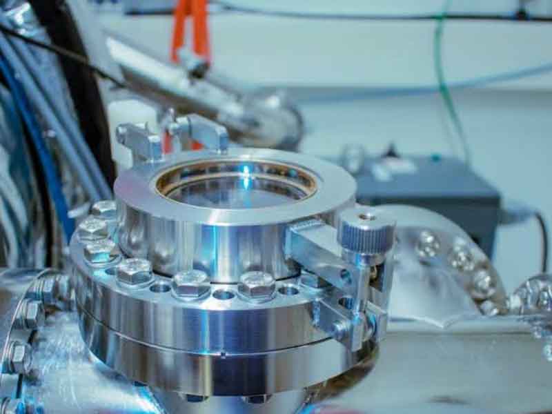
Custom semiconductor vacuum parts are the precision-machined chamber bodies, interface flanges, electrostatic chuck components, ceramic structural parts, internal liners, feed-throughs and accessory hardware that create and maintain the controlled low-pressure environment used for deposition, etching, implantation, annealing, epitaxy and metrology equipment.
The physics of vacuum technology imposes machining requirements on semiconductor vacuum chamber parts that have no analog in atmospheric-pressure precision machining. Every material surface inside a vacuum system — every machined bore, every flange face, every threaded feature, every welded joint — is simultaneously a potential source of gas molecules that desorb from the surface and return to the vacuum space, degrading the vacuum level achieved by the pumping system. This outgassing from machined surfaces is the primary limiting factor in reaching high vacuum (HV, 10⁻⁶ Torr) and ultra-high vacuum (UHV, 10⁻⁹ Torr). CNCPioneer's vacuum chamber parts programs apply these vacuum engineering requirements as primary manufacturing specifications — ASTM E595 TML ≤0.01% as the outgassing acceptance criterion, Ra 0.4μm on vacuum-wetted surfaces as the minimum surface finish standard, electropolished 304L or 316L as the default UHV material, and 100% visual inspection under 10× magnification for surface defects.
-
Outgassing compliance as primary manufacturing specification Most precision machining facilities treat ASTM E595 outgassing compliance as a customer-specified requirement they pass on to material suppliers without verification. CNCPioneer's vacuum chamber parts programs specify the complete outgassing compliance pathway — material grade, surface treatment, cleaning protocol, and packaging — and document ASTM E595 TML compliance per surface treatment batch as standard deliverable.
-
CF flange knife edge as vacuum sealing precision discipline The ConFlat knife edge is the sealing element of the most widely used UHV flange standard — its ±0.020mm profile accuracy and Ra 0.1μm surface finish govern whether the copper or aluminum gasket flows into correct contact with the knife edge under bolt torque, creating the metal-to-metal hermetic seal that maintains UHV below 10⁻⁹ Torr. CNCPioneer achieves knife edge Ra 0.1μm by optimizing finish-turning parameters.
-
Single-setup bore concentricity for multi-port flanges Process chamber flanges with multiple ports must locate all port bore axes in correct geometric relationship to the chamber bore axis. CNCPioneer's multi-port vacuum flange programs machine all port bores in single C-axis indexed MAZAK programs from the chamber bore datum — achieving port bore true position ±0.050mm from bore axis and port bore parallelism to chamber axis ±0.01° without accumulated re-fixture error.
-
Vacuum cleanliness and functional verification Vacuum programs can include ASTM E595 TML records, CMM dimensional reports, knife-edge and surface-finish profilometry, electropolish pre/post measurements, visual inspection, vacuum decay or pressure-decay test records and lot traceability.

Why CNCPioneer — Semiconductor
Vacuum Parts Manufacturer
CNCPioneer combines outgassing documentation, CF knife-edge precision, single-setup concentricity, electropolish coordination and a broad semiconductor vacuum parts portfolio. The inspection and cleanliness plan follows the pressure regime, process chemistry, material, geometry and OEM documentation requirements.
Outgassing Compliance as Primary Specification
Most precision machining facilities treat ASTM E595 outgassing compliance as a customer-specified requirement they pass on to material suppliers without verification. CNCPioneer's vacuum chamber parts programs specify the complete outgassing compliance pathway — material grade, surface treatment, cleaning protocol, and packaging — and document ASTM E595 TML compliance per surface treatment batch as standard deliverable.
CF Flange Knife Edge Precision Discipline
The ConFlat knife edge is the sealing element of the most widely used UHV flange standard — its ±0.020mm profile accuracy and Ra 0.1μm surface finish govern whether the copper gasket flows into correct contact with the knife edge under bolt torque, creating the metal-to-metal hermetic seal that maintains UHV below 10⁻⁹ Torr. CNCPioneer produces knife edges on 304L stainless from precision turning; profile verified by CMM optical scan and 100% visual inspection under 10× magnification before packaging.
Single-Setup Bore Concentricity
Process chamber flanges with multiple ports must locate all port bore axes in correct geometric relationship to the chamber bore axis. CNCPioneer's multi-port vacuum flange programs machine all port bores in single C-axis indexed MAZAK programs from the chamber bore datum — achieving port bore true position ±0.050mm from bore axis and port bore parallelism to chamber axis ±0.01° without the accumulated re-fixture error of multi-setup boring.
Electropolish Coordination as Integrated Service
Electropolishing is the mandatory surface treatment for UHV vacuum chamber parts. CNCPioneer coordinates electropolish through qualified partners as an integrated step in the manufacturing program — parts machined with electropolish material removal allowance (10–30μm per side) incorporated in machined dimensions, sent directly from CNCPioneer's precision machining to the electropolish bath without intermediate handling, and delivered as electropolished parts with post-electropolish dimensional verification.
Complete Vacuum Chamber Parts Portfolio
CF flanges (DN16CF through DN400CF), KF flanges (KF16 through KF50), ISO-K flanges (DN63 through DN500), chamber bodies, liners, electrode assemblies, substrate heater platforms, wafer chucks, load lock door mechanisms, and differential pumping manifolds — all from one China vacuum chamber parts manufacturers facility under one IATF 16949/AS9100D quality system.
Vacuum Parts Documentation and Cleanliness Control
Vacuum chamber parts programs can include material certificates, ASTM E595 batch records, cleaning and packaging records, CMM and profilometry reports, electropolish dimensional verification, vacuum decay or pressure-decay results and Certificate of Conformance documentation.
Semiconductor Vacuum Chamber Parts
— Complete Product Portfolio
CNCPioneer's semiconductor vacuum chamber parts programs cover the complete precision vacuum hardware architecture of semiconductor equipment — from ConFlat CF flanges and ISO-KF/ISO-K components through chamber bodies, internal liners, electrode assemblies, substrate heater platforms, and differential pumping manifolds.

ConFlat (CF) Flange Components
The ConFlat flange is the universal standard for UHV semiconductor equipment connections — the bolted flange pair that seals with a soft metal knife-edge-deformed gasket to achieve leak rates below 10⁻¹¹ Torr·L/s. CF flange body standard sizes DN16 through DN400 per ISO 3669. Knife edge profile: 70° included angle ±0.5°; tip radius ≤0.1mm (CNCPioneer achieves 0.05–0.08mm); knife edge radial position ±0.020mm; knife edge height 1.0–1.5mm ±0.050mm; knife edge surface finish Ra 0.1μm. Additional features: tap-off port threads M5–M8 ±0.005mm; viewport insert bore ±0.020mm; feed-through bore ±0.005mm. Material: 304L stainless standard; 316L for halogen gas service. Surface: electropolish to Ra ≤0.2μm; ASTM E595 TML ≤0.010%.

ISO-KF (Quick-Flange) Components
ISO-KF components are the standard for rough-to-medium vacuum connections in semiconductor equipment — quick-release centering ring and clamp connections enabling rapid reconfiguration of vacuum plumbing. KF16 through KF50 flange bodies: flange OD per ISO 2861; bore ID nominal tube OD; seal groove width ±0.030mm and depth ±0.020mm for Viton O-ring compression 20–25%; face flatness 0.020mm; clamp groove ±0.050mm. KF tee bodies, cross bodies, and elbows: all bores concentric at intersection ±0.100mm; bore axes in correct angular relationship ±0.05°. Material: 304L stainless standard; 6061-T6 aluminum anodized for lightweight manifold bodies; PEEK for chemically isolated connections.

ISO-K Flange Components
ISO-K flanges are the medium-vacuum-to-HV standard for larger semiconductor equipment connections — the bolt-and-clamp flange system sealing with elastomeric O-rings in the 10⁻⁸ Torr range (with Viton) or with aluminum gaskets for baked systems. Sizes DN63 through DN500 per ISO 1609. O-ring groove ±0.020mm width and depth; bolt hole pattern ±0.020mm true position (all holes C-axis indexed from bore datum in single setup); clamp groove ±0.050mm; mating face flatness 0.010mm. Special: ISO-K large-bore flanges for turbo-molecular pump inlet (DN250 and DN320) — bore ±0.050mm; face flatness 0.010mm. Material: 304L or 316L stainless; 6061-T6 aluminum with clear anodize.

Vacuum Chamber Body Components
Process chamber body: chamber bore ±0.100mm; flange face ports each bore ±0.050mm true position from chamber center; face flatness 0.010mm per port; port angular positions ±0.1°; substrate support platform flatness 0.020mm; wall thickness ±0.500mm standard. Load lock chamber body: dual-door seating faces co-planar within 0.020mm; door frame flatness 0.010mm; robot arm channel bore ±0.050mm; wafer cassette position features ±0.100mm. Transfer chamber body: large-bore main chamber Ø400–Ø1,000mm; multiple slot valve port flanges at robot arm angle positions ±0.25°; robot lift mechanism bore ±0.050mm. Material: 316L stainless for corrosive processes; 6061-T6 hard anodize for non-corrosive processes.

Vacuum Chamber Internal Components
Substrate heater platform: wafer seating surface flatness 0.050mm for Ø200mm and Ø300mm wafers; heater element channel ±0.100mm; temperature sensor bore ±0.020mm; lift pin holes ±0.050mm diameter, ±0.100mm true position. Electrostatic chuck (ESC) housing: electrode bore concentricity ±0.003mm; helium backside gas channels ±0.020mm width; high-voltage feed-through bore ±0.005mm. Chamber liner: liner OD ±0.100mm; inner surface Ra 1.6–3.2μm; liner split joints gap ≤0.200mm. Electrode assemblies: electrode face Ra 0.8μm, flatness 0.020mm; feed-through bore ±0.005mm; cooling channel ±0.100mm; 100% pressure decay leak test at 3× rated pressure. Material: 6061-T6, 316L, molybdenum, graphite per application.

Vacuum Instrumentation & Manifold Components
Vacuum gauge port flanges: ion gauge port DN40 CF standard; gauge tube bore ±0.050mm concentric to flange bore ±0.020mm; capacitance manometer port flatness 0.005mm; RGA port line-of-sight bore to chamber center ±0.5mm. Injection valve port flanges: VCR fitting bore ±0.010mm; gas channel bore ±0.050mm; Ra 0.4μm for low-adsorption gas delivery path. Differential pumping manifold bodies: 3–7 coaxial bores on common centerline ±0.050mm; pumping port bores KF or CF at each stage ±0.050mm; aperture bores ±0.020mm diameter, concentricity ±0.020mm. Turbomolecular pump inlet adapter flanges: TMP inlet bore ±0.050mm; chamber side face flatness ±0.010mm; knife edge ±0.020mm profile (CF side). Material: 304L stainless for UHV-compatible adapters.
Industries & Applications
CNCPioneer's semiconductor vacuum chamber parts serve every industry consuming precision vacuum hardware at UHV tolerances — from semiconductor capital equipment OEMs and PVD/CVD equipment manufacturers to etch system producers, ion implantation builders, MBE system builders, and research institutions.

Semiconductor Capital Equipment OEMs
Complete semiconductor vacuum chamber parts programs — CF flange libraries for all port sizes, process chamber body machining, load lock chamber bodies, transfer chamber components, electrode assemblies, and chamber liner sets — coordinated for semiconductor equipment assembly schedules. Single China vacuum chamber parts manufacturers supply relationship covering the complete vacuum hardware BOM.
PVD and CVD Equipment Manufacturers
316L process chamber bodies and liner components for physical and chemical vapor deposition systems — halogen-resistant stainless for CVD silane and NF₃ cleaning environments; substrate pedestal platforms with heater element channels; CF pump port flanges; and electrode RF feed-through flanges with ceramic isolation.

Etch System Producers
Halogen-resistant 316L chamber bodies and internal components for silicon and dielectric etch systems — inductively and capacitively coupled plasma etch chamber liner sets; electrode assemblies; ESC housing bodies; and CF and ISO-K flange port arrays.
Ion Implantation Equipment Builders
UHV beam line components for ion implantation systems — differential pumping manifold bodies with coaxial aperture bore arrays; analyzer chamber body segments; Faraday cup and beam dump housing machining; and CF flange arrays for beam line connection ports.
MBE and Epitaxy System Builders
Ultra-high vacuum chamber bodies and internal components for molecular beam epitaxy systems — 316L UHV growth chamber bodies; RHEED gun and diffraction screen port flanges; effusion cell port flanges; cryopanel mounting structures; and UHV substrate heater platforms in refractory materials.
Wafer Inspection and Metrology Instruments
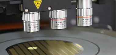
High vacuum chamber components for wafer surface inspection, CD-SEM, defect review SEM, and optical CD metrology instruments — HV load lock body components; sample stage chamber parts; optical viewport CF flanges; and vacuum-compatible sensor housing bodies.
CNC Machining Process for
Semiconductor Vacuum Chamber Parts
CNCPioneer's semiconductor vacuum chamber parts process runs on 66+ MAZAK Integrex and Quick Turn mill-turn machining centers, MAZAK VARIAXIS 5-axis platforms, and 78+ Swiss CNC lathes — with material preparation and cleanliness protocols that establish vacuum compliance from the first machining operation.
Material Preparation & Cleanliness Protocol
Material certification review: EN 10204 3.1 mill certificate verified for grade compliance; SII XRF spot check on bar end confirming composition. Pre-machining cleaning: billet solvent-cleaned to remove mill scale protective oil before entering machining area. Cutting fluid selection: water-soluble cutting fluid (not petroleum-based) used for all vacuum chamber parts turning — petroleum-based fluids leave hydrocarbon residues that are extremely difficult to remove. Post-machining cleaning: ultrasonic clean in DI water + alkaline detergent → DI rinse → IPA wipe → N₂ dry before electropolish or packaging. Handling: cleanroom gloves mandatory; no bare-hand contact with vacuum-wetted surfaces after cleaning.
Precision Turning Sequence for CF Flanges
Bar stock facing and centering → rough bore to −0.3mm stock → rough OD and body profile → rough knife edge to −0.1mm → 30-minute thermal stabilization → finish bore single-pass to ±0.010mm (before EP allowance) → finish OD single-pass → finish knife edge: single-pass CBN turning at v_c = 120 m/min, f = 0.04mm/rev producing Ra 0.1μm; verified by in-process profilometer → C-axis bolt holes all from bore datum ±0.010mm → tap-off port threads ±0.005mm pitch diameter → part-off via sub-spindle → initial 10× visual inspection of knife edge before electropolish.
Electropolish Coordination & Post-Treatment Verification
Pre-EP dimensional record: CMM all critical dimensions before electropolish; EP will remove 10–30μm per side. Surface electropolish: phosphoric-sulfuric acid bath at 70–80°C, 20–40 A/dm² for 10–20μm material removal, achieving Ra ≤0.2μm. Post-EP cleaning: citric acid passivation → DI rinse → IPA wipe → N₂ dry → cleanroom bag packaging at EP facility. Post-EP dimensional verification: CMM re-measurement confirming post-EP dimensions within specification. Post-EP Ra verification: profilometer on knife edge (Ra ≤0.1μm), flange face (Ra ≤0.2μm), and bore (Ra ≤0.2μm). Final 10× visual inspection post-EP for pitting or preferential etching.
Chamber Body Machining
Process chamber body: chamber bore ±0.100mm; flange face ports each bore ±0.050mm true position from chamber center; face flatness 0.010mm per port; port angular positions ±0.1°; substrate support platform flatness 0.020mm; internal gas distribution ring groove ±0.050mm; wall thickness ±0.500mm standard. Load lock: dual-door seating faces co-planar within 0.020mm; door frame flatness 0.010mm; robot arm channel bore ±0.050mm; wafer cassette position features ±0.100mm. Transfer chamber: large-bore main chamber Ø400–Ø1,000mm; multiple slot valve port flanges at robot arm angle positions ±0.25°; robot lift mechanism bore ±0.050mm.
In-Process Control & Final Inspection
CF knife edge Ra profilometry immediately after finish turning — verified at Ra ≤0.1μm before proceeding to C-axis bolt holes; non-compliant knife edge is reworked by single additional finish pass. Multi-bore chamber flanges: CMM measurement of first three port bores before completing remainder — confirms C-axis indexing maintains position accuracy. Electropolish dimension budget tracking: pre-EP CMM dimensions recorded; EP material removal calculated from post-EP re-measurement; dimensional margin to tolerance verified before shipment. Final: CMM all bore diameters, CF knife edge radial position, face flatness, bolt circle true position, port bore positions; profilometry knife edge Ra, vacuum-wetted bore Ra, flange face Ra; 10× magnification visual of CF knife edge on 100% of flanges; thread gauges all tap-off port threads.
IATF 16949 / AS9100D Documentation
Certificate of Conformance · CMM dimensional report: all bore diameters, knife edge position, face flatness, bolt circle true position, port bore positions · Profilometry: knife edge Ra, vacuum-wetted bore Ra, flange face Ra · ASTM E595 TML batch certificate per surface treatment lot · Visual inspection records per CF flange · Electropolish pre/post dimensional verification records · Material certificates with lot traceability · Thread gauge records · PPAP Level 3 for OEM programs · FAIR per AS9102 for aerospace and defense programs · All records retained 20 years.
Materials for Semiconductor
Vacuum Chamber Parts
Semiconductor vacuum chamber parts material selection is governed by outgassing rate, vacuum pressure regime, process chemistry compatibility, thermal requirements, and magnetic properties. 304L and 316L stainless steel electropolished are the default UHV materials — ASTM E595 TML ≤0.01% and steady-state outgassing ~10⁻¹² Torr·L/s·cm² after bake.
Stainless 304L
ASTM E595 TML ≤0.01% (EP) · Outgassing ~10⁻¹² Torr·L/s·cm² (baked) · Standard UHV; weldable; non-magnetic. 304L stainless (EN 1.4306; UNS S30403) is the default material for CF flanges, chamber bodies, and transfer chambers. Low carbon (≤0.030%) prevents sensitization at weld temperatures; austenitic FCC structure is non-magnetic. Electropolished to Ra ≤0.2μm achieves TML ≤0.01% — the lowest outgassing of common housing materials. Standard passivation ASTM A967 mandatory.
Stainless 316L
ASTM E595 TML ≤0.01% (EP) · Outgassing ~10⁻¹² Torr·L/s·cm² (baked) · Halogen resistance; Mo addition. 316L contains 2.0–3.0% molybdenum, providing superior resistance to pitting corrosion in halide environments (fluorine, chlorine process gases encountered in etch and CVD chambers). For dry-process semiconductor chambers where halogen gas contacts the chamber body — silicon etch in SF₆ or Cl₂ plasma — 316L is required. Identical outgassing performance to 304L after electropolish.
Stainless 17-4PH H900
ASTM E595 TML ≤0.01% · CTE 10.8 ppm/°C · High strength; corrosion resistant. Martensitic precipitation-hardened stainless steel for high-strength sensor mount and housing structures where 316L's yield strength is insufficient. H900 aging to HRC 44–47 produces 1,310 MPa yield strength — the strength of alloy steel with the corrosion resistance of stainless. Passivation mandatory; electropolish available for UHV programs requiring both strength and lowest outgassing.
Aluminum 6061-T6
ASTM E595 TML ≤0.020% (anodize) · Outgassing ~10⁻¹¹ Torr·L/s·cm² · Lightweight; thermal; machinable. Specified for load lock chamber bodies, liner components, and heater platforms where aluminum's high thermal diffusivity enables rapid pump-down cycle by minimizing thermal gradient during cooling after venting. Type II clear anodize seals aluminum pores that would otherwise absorb and slowly release oil and water; TML ≤0.020% after anodize (versus 0.080–0.150% for machined unprotected aluminum). Anodize growth allowance (5–10μm per side) incorporated in machined bore dimensions.
Aluminum 6061-T6 Type III Hard Anodize
HV 400+ wear resistance for aluminum process chamber liner inner surfaces — reduces particle generation from handling contact; black hard anodize reduces thermal emissivity for radiation shielding applications within process chambers. Type III anodize growth allowance machined into bore finish dimension; post-anodize bore air gauge confirms final bore within specification. Standard for aluminum-process-compatible chamber liners where film adhesion control is critical.
Copper OFC C10100
ASTM E595 TML ≤0.005% · Outgassing ~10⁻¹³ Torr·L/s·cm² · CF gasket material; thermal; sealing. Oxygen-free high-conductivity copper is the standard CF gasket material — soft enough for knife edge cold-welding (yield 70 MPa annealed), high thermal conductivity for heat spreading, and extremely low outgassing after proper cleaning. CNCPioneer machines OFHC copper CF gaskets to standard CF sizes with OD and ID tolerances matching flange bore and knife edge contact radius.
Titanium Grade 2 CP
ASTM E595 TML ≤0.010% · Outgassing ~10⁻¹³ Torr·L/s·cm² · Low hydrogen permeation; non-magnetic; strong. Specified for UHV sub-assemblies and titanium sublimation pump (TSP) housing bodies where low hydrogen permeation through the chamber wall is critical. Non-magnetic (μᵣ ≈ 1.0005) satisfies MRI-compatibility and electron beam column requirements. Lower outgassing than stainless steel at equivalent surface finish; machining requires reduced cutting speeds to prevent work-hardening.
Kovar (UNS K94610)
ASTM E595 TML ≤0.01% · CTE 5.2 ppm/°C · CTE matches glass/ceramic. Specified for viewport flanges and glass-metal seal configurations — Kovar's CTE 5.2 ppm/°C matches borosilicate glass (CTE 3.3 ppm/°C) and aluminum oxide ceramic (CTE 6.5 ppm/°C) closely enough that glass-to-Kovar hermetic seals maintain integrity through −65°C to +150°C temperature cycling. Gold plating (0.5–2.0μm) for hermetic seal cleanliness and solder-ability.
Inconel 625
ASTM E595 TML ≤0.010% · Outgassing ~10⁻¹² Torr·L/s·cm² · High-temperature; halogen resistant. Nickel-based superalloy for high-temperature process chamber parts where 316L's strength degrades above 600°C. Excellent resistance to oxidation and carburization at elevated temperatures; maintains mechanical strength and corrosion resistance in aggressive process environments including halogen and sulfur-containing gases. Machining requires rigid setups and ceramic inserts due to work-hardening tendency.
PEEK (Victrex 450G)
ASTM E595 TML ≤0.030% · Outgassing ~10⁻¹² Torr·L/s·cm² · Insulating; chemical resistant; machinable. Specified for feed-through insulators, valve seats, and chemically isolated KF connections where electrical isolation between components is required, or where aggressive chemical environments would attack metal housings. PEEK achieves TML ≤0.03% without surface treatment — inherently low outgassing polymer. Machinable to ±0.002mm bore and OD tolerance; no post-machining heat treatment required.
Macor (Corning)
ASTM E595 TML ≤0.020% · Outgassing ~10⁻¹² Torr·L/s·cm² · Machinable ceramic; insulating. Glass-ceramic material that can be machined with conventional carbide tooling to tight tolerances without firing or grinding — ideal for feed-through insulators, spacer elements, and structural ceramic components in vacuum systems where conventional ceramics would require diamond grinding. Zero porosity after machining; can be metallized for brazing to metal vacuum flanges.
Molybdenum TZM Alloy
ASTM E595 TML ≤0.005% · Outgassing ~10⁻¹³ Torr·L/s·cm² · Refractory; low vapor pressure. Specified for high-temperature heater elements, aperture bodies, and substrate support components in MBE and CVD systems operating above 1,000°C where stainless steel and aluminum are inadequate. TZM (titanium-zirconium-molybdenum) alloy provides improved creep resistance and recrystallization temperature over pure molybdenum. Extremely low vapor pressure at operating temperature; machining requires EDM or grinding for complex geometries.
Surface Treatments for
Semiconductor Vacuum Chamber Parts
Semiconductor vacuum chamber parts surface treatment selection addresses outgassing compliance, vacuum pressure regime, corrosion resistance, and surface area reduction — with coating allowances machined into precision dimensions and verified post-treatment.
Electropolish (EP) — Mandatory UHV Treatment
Electrochemical material removal on 304L and 316L stainless vacuum chamber parts — the surface treatment that defines semiconductor UHV equipment manufacturing. Pre-EP surface finish requirement: Ra ≤0.8μm machined (CNCPioneer achieves Ra 0.4μm standard; knife edge Ra 0.1μm). EP material removal: 10–20μm per side incorporated in machined dimension allowance. Post-EP surface finish: Ra ≤0.2μm on general vacuum-wetted surfaces; Ra ≤0.1μm on knife edge. Post-EP passive layer: chromium-rich (Cr₂O₃) passive oxide — superior corrosion resistance and reduced catalytic activity for gas adsorption. ASTM E595 compliance after EP: TML ≤0.010% on 304L/316L. CNCPioneer coordinates EP at qualified facilities; parts transferred directly without intermediate handling; post-EP dimensional verification before packaging.
Passivation — ASTM A967
Citric acid or nitric acid passivation on non-electropolished stainless surfaces (external surfaces, non-vacuum-wetted zones) — removes free iron from machined surface, preventing flash rusting in humid storage environments. For UHV parts: passivation on external surfaces only; EP on vacuum-wetted surfaces. Zero dimensional change; ASTM E595 compliant after passivation + cleaning. Applied after all machining is complete including cross-holes, grooves, threads, and bores; passivation liquid penetrates all internal features uniformly. Passivation certificates included in standard shipment documentation.
Type II Clear Anodize — MIL-A-8625 (Aluminum HV Parts)
6061-T6 aluminum load lock bodies, liner components, and heater platforms with Type II clear anodize — seals aluminum pores that would otherwise absorb and slowly release oil and water; ASTM E595 TML ≤0.020% after anodize (versus 0.080–0.150% for machined unprotected aluminum). Anodize growth allowance (5–10μm per side) incorporated in machined bore dimensions as standard. Electrically insulating; optically neutral; corrosion protection for sealed indoor vacuum joint environments.
Type III Hard Anodize (Aluminum Chamber Liners)
HV 400+ wear resistance for aluminum process chamber liner inner surfaces — reduces particle generation from handling contact; black hard anodize reduces thermal emissivity for radiation shielding applications within process chambers. Type III anodize growth allowance machined into bore finish dimension; post-anodize bore air gauge confirms final bore within specification. Critical for aluminum-process-compatible chamber liners where film adhesion control and particle suppression determine wafer yield.
Gold Plating (Kovar and Copper Components)
0.5–2.0μm gold electroplate on Kovar semiconductor vacuum chamber parts for hermetic seal cleanliness and solder-ability; on copper EMI shielding elements for oxidation prevention. Gold plating provides ASTM E595 compliant surface; solder-wettable for component attachment. Critical for Kovar hermetic housing programs where glass-to-metal seals require clean, oxide-free surfaces for reliable sealing integrity through −65°C to +150°C temperature cycling.
Vacuum Bake Outgassing (UHV Pre-Assembly)
150–250°C bake under vacuum (10⁻⁷ Torr) for 24–48 hours before UHV equipment commissioning — dramatically reduces physisorbed water from stainless surfaces, enabling faster pump-down to UHV baseline. CNCPioneer coordinates vacuum bake at qualified facilities on request for fully electropolished vacuum chamber part sets. Baking accelerates hydrogen diffusion and desorption by orders of magnitude, reducing bulk hydrogen inventory to achieve UHV baseline pressure in 24–48 hours rather than 2–4 weeks of room-temperature pumping.
All surface treatments on semiconductor vacuum chamber parts programs — electropolish (Ra ≤0.2μm, TML ≤0.010%), passivation ASTM A967, Type II/III anodize (TML ≤0.020%), gold plate, and vacuum bake — are documented with treatment certifications and post-treatment dimensional verification in the shipment package. Plating and coating allowances are machined-in to critical dimensions at the CNC stage and confirmed post-treatment by CMM or profilometry.
Quality Assurance for
Semiconductor Vacuum Chamber Parts
CNCPioneer's semiconductor vacuum chamber parts quality assurance addresses the vacuum engineering requirements of outgassing compliance, CF knife edge precision, multi-port concentricity, and surface cleanliness — with documented verification at every process stage.
Vacuum Engineering DFM Review (24 Hours)
Every semiconductor vacuum chamber parts inquiry receives vacuum engineering DFM covering: outgassing compliance specification from operating pressure regime (rough/HV/UHV); material grade selection for process chemistry compatibility; electropolish allowance incorporation in critical bore and face dimensions; CF knife edge profile feasibility for standard and non-standard CF sizes; multi-port angular position network analysis for chamber body programs; weld prep geometry for electron beam and TIG-welded assemblies; and ASTM E595 compliance documentation pathway.
Material Incoming Inspection
SII XRF composition verification on every 304L lot (C ≤0.030% confirmed; Cr 18.0–20.0%; Ni 8.0–12.0%) and 316L lot (Mo 2.0–3.0%; C ≤0.030%). EN 10204 3.1 mill certificates received and archived. Surface condition visual: no mechanical damage on bar or plate ends at critical machining zones. Hardness verification post-aging and post-heat-treatment per lot before final machining.
Precision In-Process Controls
CF knife edge Ra profilometry immediately after finish turning — verified at Ra ≤0.1μm before proceeding to C-axis bolt holes; non-compliant knife edge surface finish is reworked by single additional finish pass. Multi-bore chamber flanges: CMM measurement of first three port bores before completing remainder of bolt circle — confirms C-axis indexing maintains position accuracy. Electropolish dimension budget tracking: pre-EP CMM dimensions recorded; EP material removal calculated from post-EP re-measurement; dimensional margin to tolerance verified before shipment release.
Final Inspection
CMM (±0.001mm): all bore diameters, CF knife edge radial position, face flatness, bolt circle true position, port bore true positions and angular positions, weld bevel geometry. Profilometry: knife edge Ra (≤0.1μm); vacuum-wetted bore Ra (≤0.2μm post-EP or ≤0.4μm pre-EP); flange face Ra. Visual inspection: 10× magnification of CF knife edge on 100% of flanges — scratches, pits, tool marks logged per flange serial number; rejection for defects >0.1mm on knife edge. Thread gauges: GO/NO-GO all tap-off port threads.
Volume Production & PPAP
PPAP Level 3 for semiconductor vacuum chamber parts OEM programs: CF knife edge profile and bore diameter Cpk ≥1.67 (IATF special characteristics); face flatness and feature positions Cpk ≥1.33; MSA Gage R&R on profilometer and CMM measurement systems ≤10% gauge variation; complete PPAP package including dimensional results, PSW, PFMEA, control plan, and process flow. Volume production at 2-week monthly blanket releases with dedicated capacity and safety stock.
Documentation Package
Certificate of Conformance · CMM dimensional report · Profilometry records · Material certificates with lot traceability · ASTM E595 TML batch certificate per surface treatment lot · Visual inspection records per CF flange · Electropolish pre/post dimensional verification records · Thread gauge records · PPAP Level 3 for OEM programs · FAIR per AS9102 for aerospace and defense programs · All records retained 20 years.
Dimensional Specifications & Industry Standards
CNCPioneer's semiconductor vacuum chamber parts dimensional specifications and industry standards compliance establish the documented precision and vacuum compatibility that semiconductor equipment OEMs require for cleanroom-deployed instrumentation and process equipment.
Dimensional Specifications
CF bore diameter ±0.020mm (UHV) via CMM. CF knife edge profile ±0.020mm via CMM optical scan. CF knife edge Ra Ra 0.1μm via profilometry. CF face flatness 0.005mm via CMM. CF bolt circle true position ±0.010mm via CMM. KF O-ring groove width ±0.015mm via CMM. ISO-K O-ring groove depth ±0.015mm via CMM. Port bore true position ±0.030mm via CMM. Port bore angular position ±0.1° via CMM. Multi-bore concentricity ±0.020mm via CMM. Vacuum-wetted surface Ra ≤0.2μm (EP) via profilometry.
- CF knife edge ±0.020mm
- Knife edge Ra 0.1μm
- Face flatness 0.005mm
Vacuum & Industry Standards
ISO 3669 — CF (ConFlat) flange dimensions and tolerances; DN16 through DN400. ISO 2861 — KF (quick-flange) dimensions; KF10 through KF50. ISO 1609 — ISO-K flange dimensions; DN63 through DN500. ASTM E595 — TML ≤0.01% standard for UHV; ≤0.05% for HV. ISO 14644 — Cleanroom classification and contamination control. ASTM A967 — Passivation of stainless steel components. AWS D1.6 — Structural welding code for stainless steel. ASME IX — Welding qualifications. SEMI E1 — SEMI standard for mechanical interface. SEMI S2 — Environmental, health, and safety guideline.
- ISO 3669 / 2861 / 1609
- ASTM E595 TML ≤0.01%
- SEMI E1 / SEMI S2
Quality Management Certifications
IATF 16949:2016 — Automotive-grade quality management for semiconductor vacuum chamber parts OEM production programs. AS9100D — Aerospace quality for defense-related semiconductor equipment vacuum chamber parts. ISO 10012:2003 — Measurement management certified. IEC 61010-1 — Safety requirements for electrical equipment in semiconductor measurement and test instruments. All quality systems audited and maintained at CNCPioneer's Shenzhen facility.
- IATF 16949:2016 Certified
- AS9100D Certified
- ISO 10012:2003 Certified
Production Programs & Lead Times
Prototype: standard DN40 CF flange 304L electropolished — 5–7 business days; KF16–KF50 flange — 5–7 days; load lock chamber body 6061-T6 anodized — 8–12 days; process chamber liner 316L EP — 7–10 days; multi-port process chamber flange — 8–14 days; differential pumping manifold — 8–12 days. Volume: 50–500 units −30–45%; 501–2,000 units −45–58%; 2,001–10,000 units −58–66%; 10,001–50,000 units −66–72%; 50,000+ units maximum discount with dedicated capacity.
- Prototype: 5–14 business days
- PPAP Level 3: 6–8 weeks
- Volume: 2-week monthly releases
Semiconductor Vacuum Chamber Parts FAQ
Common questions from semiconductor equipment OEMs, PVD/CVD equipment manufacturers, etch system producers, ion implantation equipment builders, and MBE system builders about CNCPioneer's vacuum chamber parts, CF/KF/ISO-K interfaces, electrostatic chuck components, ceramic structural parts, material selection and electropolish coordination.
The grade distinction is critically important for semiconductor vacuum chamber parts. The L grades (304L and 316L) differ from their non-L equivalents (304 and 316) in one critical specification: maximum carbon content is ≤0.030% for L-grades versus ≤0.080% for standard grades. This carbon content difference has two vacuum-relevant consequences. First, sensitization prevention: when stainless steel is heated to 425–870°C (during TIG or orbital welding of CF flanges to chamber bodies, during electropolish bath heating, or during vacuum bake), carbon migrates to grain boundaries and precipitates as chromium carbide (Cr₂₃C₆). This depletes the chromium surrounding each grain boundary below 12% — the minimum for passivity — creating narrow "sensitized" zones of reduced corrosion and chemical resistance that are preferentially attacked by process gas environments and produce elevated local outgassing from the carbide-enriched boundaries. L-grades, with ≤0.030% carbon, contain insufficient carbon for significant Cr₂₃C₆ precipitation even after welding, preserving uniform corrosion resistance throughout the vacuum-wetted surface. Second, electropolish uniformity: standard-grade (non-L) stainless with higher carbon content shows pronounced grain boundary etching during electropolish — the EP bath preferentially attacks carbide-enriched grain boundaries, producing a textured surface with visible grain boundary channels at Ra ≤0.2μm nominal finish. These channels are elevated outgassing sites and micro-leakage paths at CF knife edge contacts. L-grade stainless electropolishes uniformly without grain boundary preferential etching, achieving the smooth Ra ≤0.1μm finish required for reliable CF knife edge sealing. CNCPioneer specifies and verifies (by SII XRF C-content measurement) 304L and 316L grades for all semiconductor vacuum chamber parts — rejecting 304 and 316 substitutions even when chemical composition is otherwise identical.
The ConFlat sealing mechanism is a cold-weld metal-to-metal seal formed by plastic deformation of a soft metal gasket (copper, OFHC oxygen-free high-conductivity, or aluminum) between two stainless steel knife edges. When CF flanges are bolted together, the knife edge tip (≤0.1mm tip radius) penetrates the soft gasket surface under bolt clamping load — the contact stress at the knife edge tip exceeds the copper gasket's yield strength (70 MPa for annealed OFHC copper) by a factor of 10–20×, causing the copper to flow plastically around the knife edge profile and fill any surface micro-irregularities, creating a gas-tight metal-to-metal bond across the full 360° knife edge contact circumference. The seal achieves leak rates below 10⁻¹¹ Torr·L/s — equivalent to one helium molecule per second passing through the seal — when the following machining accuracy conditions are simultaneously met. First, knife edge profile ±0.020mm radial position: the knife edges on both mating flanges must engage the copper gasket at the same radial position simultaneously — if one flange's knife edge is 0.030mm further out than the other, the outer knife edge makes contact first, exhausting bolt torque before the inner knife edge contacts the gasket, leaving a high-pressure gas leak path at the unsealed inner knife edge zone. Second, knife edge Ra ≤0.1μm: surface scratches or machining marks on the knife edge face create micro-channels in the deformed copper gasket at the scratch locations — a single 0.2μm-deep scratch 1mm long across the knife edge face produces a micro-channel in the deformed copper that leaks at approximately 10⁻⁸ Torr·L/s, making UHV below 10⁻⁹ Torr impossible to achieve at that flange joint. Third, flange face flatness 0.005mm: non-flat flange faces cause the bolt torque to be distributed non-uniformly around the bolt circle, with bolts at the high-face zones reaching the correct gasket deformation torque while bolts at low-face zones are under-torqued — producing insufficient gasket deformation at the low zones and a leak path. CNCPioneer achieves all three requirements simultaneously — knife edge position ±0.020mm, knife edge Ra 0.1μm, face flatness 0.005mm — through the dedicated knife edge turning protocol, verified by profilometry per flange lot and visual inspection under 10× magnification per individual flange.
CNCPioneer's electropolish coordination for UHV semiconductor vacuum chamber parts is an integrated multi-step process, not simply a subcontracting activity. The coordination sequence: machining of all vacuum-wetted surfaces to Ra ≤0.4μm pre-EP (knife edges to Ra ≤0.1μm pre-EP) and to dimensions incorporating 10–20μm per side EP material removal allowance; ultrasonic cleaning in DI water + alkaline detergent immediately after final machining to remove cutting fluid residues before they polymerize on the stainless surface; transport to qualified EP partner in sealed cleanroom bags within 24 hours of final cleaning; electropolish by the EP partner in phosphoric-sulfuric acid bath at controlled temperature (70–80°C) and current density (20–40 A/dm²) for time calculated to produce 10–20μm material removal and achieve Ra ≤0.2μm; citric acid passivation after EP; DI water rinse; IPA wipe; N₂ dry; cleanroom bag packaging at EP facility; return to CNCPioneer for post-EP dimensional verification and final inspection. The ASTM E595 TML documentation chain: the EP partner performs ASTM E595 TML testing on representative coupons of 304L and 316L processed in the same bath chemistry, temperature, and time as the customer's parts — test reports confirming TML ≤0.010% from the electropolished surface condition. CNCPioneer references these ASTM E595 batch test reports (one per EP bath lot, covering all parts processed in that lot) in the vacuum chamber parts Certificate of Conformance and documentation package. The documentation chain from mill certificate (C ≤0.030% confirmed) → CNCPioneer CMM dimensional report → EP partner ASTM E595 TML test report → CNCPioneer CoC provides semiconductor equipment OEMs with complete traceability from raw material to delivered vacuum chamber part, satisfying the documentation requirements of semiconductor equipment quality programs (SEMI E1, SEMI S2, and customer-specific vacuum hardware specifications).
Get a Quote for Semiconductor Vacuum Chamber Parts
Submit your semiconductor vacuum chamber parts drawing, vacuum-system specification or CF/KF/ISO-K flange requirement for a 24-hour vacuum engineering DFM and quote review. We will assess pressure regime, process chemistry, material grade, electropolish allowance, CF knife-edge feasibility, multi-port concentricity, electrostatic chuck or ceramic component requirements, ASTM E595 documentation and vacuum decay or leak-test scope.