
Custom Cylinder Head
CNC Machining
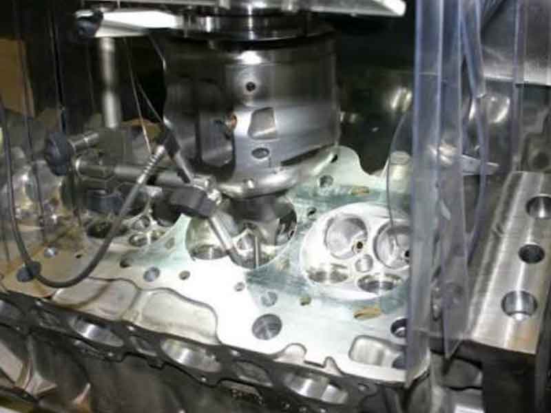
CNCPioneer is an IATF 16949 and AS9100D certified China cylinder head manufacturers facility delivering CNC cylinder head programs — custom aluminum alloy engine cylinder head bodies, industrial reciprocating compressor cylinder head assemblies, marine diesel cylinder head components, generator set cylinder head machining, racing and performance engine cylinder head programs, hydraulic and pneumatic cylinder end cap and head assemblies, and complete custom cylinder head fabrication packages — with deck surface flatness 0.010mm/300mm, valve seat bore diameter accuracy ±0.005mm, valve guide bore concentricity to seat ±0.003mm, combustion chamber volume matched to ±0.5cc per set, coolant passage bore position ±0.050mm, and bolt hole true position ±0.010mm in single-setup MAZAK mill-turn and 5-axis programs.
66+ MAZAK mill-turn centers, MAZAK VARIAXIS 5-axis platforms, and 78+ Swiss CNC lathes serving industrial engine manufacturers, reciprocating compressor OEMs, marine propulsion equipment builders, generator set producers, performance motorsport engine developers, agricultural and construction equipment OEMs, and hydraulic and pneumatic equipment manufacturers since 2011.
What Is a
Custom Cylinder Head?
A custom cylinder head is a precision-machined structural and functional engine or compressor component — machined from aluminum alloy casting, billet aluminum, cast iron, or steel — that closes the top of one or more engine or compressor cylinders, contains the combustion chamber volume, houses the intake and exhaust valve seats and guides, integrates the coolant jacket passages for thermal management, provides the structural mounting interface for the valve train mechanism, and constitutes the primary sealing interface against the cylinder block through a precision-flat deck surface whose compliance to the head gasket determines whether the combustion chamber seals reliably across the operating pressure and temperature range.
Custom cylinder heads are required when the engine or compressor design is non-standard or low-volume without a commercially available replacement; when the application demands dimensional accuracy beyond production-cast heads (combustion chamber volume-matching to ±0.5cc for balanced multi-cylinder performance); when material specification differs from original casting; when port geometry, chamber shape, or cooling passage layout requires modification; or when the original cylinder head is irreplaceable, requiring reverse engineering and precision reproduction from original-specification CNC machining.
-
Deck surface flatness 0.010mm/300mm — the primary sealing quality Non-flat deck surfaces create high and low gasket contact zones: at low spots, combustion pressure at 80–250 bar finds an inadequately seated gasket zone and initiates blowby. CNCPioneer achieves 0.010mm/300mm flatness via matched face mill inserts, thermal stabilization, single-pass finish, and CMM 25-point grid verification on every head.
-
Combustion chamber volume ±0.5cc — balanced multi-cylinder performance Each 1cc chamber volume difference produces approximately 0.3–0.5 compression ratio unit variation per cylinder. CNCPioneer’s 5-axis chamber CNC programs machine volume to ±0.5cc, verified by fluid fill measurement on every chamber with matched-set documentation.
-
Valve seat concentricity ±0.003mm — full-circumference valve sealing Non-concentricity produces asymmetric valve contact — one crescent of high stress and one of no contact — causing hot gas leakage. CNCPioneer’s single-setup pilot tooling achieves ±0.003mm TIR by mechanical registration, verified by dial indicator on every valve position.
-
40–60% China cost advantage at certified quality A billet 6061-T6 4-cylinder 4-valve-per-cylinder performance head set (matched ±0.5cc, deck 0.010mm/300mm, seat TIR ±0.003mm) costs $2,800 from a US machine shop vs. $1,550 prototype and $580–$720 at 500 annual sets at CNCPioneer.

Why CNCPioneer for
Custom Cylinder Head Machining?
Among China cylinder head manufacturers, CNCPioneer's deck surface flatness discipline at 0.010mm/300mm, combustion chamber volume matching to ±0.5cc, valve seat-to-guide concentricity at ±0.003mm by single-setup pilot tooling, complete CNC cylinder head machining sequence in integrated MAZAK programs, rapid prototype capability at 5–14 days, and 40–60% China cost advantage establish our custom cylinder head factory as the preferred supplier for industrial engine OEMs, compressor manufacturers, marine builders, motorsport programs, and hydraulic equipment producers globally.
Deck Surface Flatness 0.010mm/300mm — The Primary Sealing Quality
The cylinder head deck surface is the most functionally critical machined surface — the face that contacts the head gasket and must remain flat within 0.010mm/300mm to provide uniform gasket seating pressure across the full combustion chamber perimeter. At 180 bar peak cylinder pressure, the head lifts approximately 0.003–0.008mm at the bolt pattern boundary; this lift must stay within the head gasket's elastic recovery capability. CNCPioneer achieves 0.010mm/300mm flatness through four compounded disciplines: matched face mill inserts (all inserts within ±0.003mm height); thermal stabilization (20-minute pause after rough milling before finish milling eliminates 12–18°C surface gradient); single-pass finish (eliminating step artifacts at tool re-engagement); and CMM 25-point grid verification on every cylinder head before release.
Combustion Chamber Volume Matching ±0.5cc — Balanced Multi-Cylinder Performance
In multi-cylinder industrial and racing engines, combustion chamber volume variation between cylinders directly produces cylinder-to-cylinder compression ratio variation — each 1cc chamber volume difference produces approximately 0.3–0.5 compression ratio unit variation in a typical 500cc-per-cylinder engine. CNCPioneer's combustion chamber CNC programs machine volume to ±0.5cc from design specification, verified by fluid fill measurement (precision syringe, water-soluble oil, head sealed at deck, fluid introduced through spark plug hole, volume to known datum level measured to ±0.1cc) on every cylinder head, with matched-set documentation confirming all cylinders in a multi-cylinder set are within ±0.5cc of each other. Racing programs: ±0.3cc matched set available.
Valve Seat-to-Guide Concentricity ±0.003mm — Full-Circumference Valve Contact
Valve seat concentricity to valve guide bore governs whether the valve face contacts the seat uniformly around the full 360° circumference. Non-concentricity produces a crescent of high contact stress and a crescent of no contact — creating hot gas leakage that burns valve seats and faces in service. CNCPioneer's single-setup pilot tooling system machines seat insert bores using a seat cutter that pilots in the finished guide bore, centering the seat by mechanical registration rather than machine positioning. Concentricity is achieved regardless of thermal drift, fixture settling, or position variation — ±0.003mm TIR by direct mechanical constraint, verified by dial indicator on every valve position of every cylinder head.
Complete CNC Cylinder Head Machining Sequence — Integrated Programs
CNCPioneer's custom cylinder head programs machine the complete feature set — deck surface, combustion chambers, valve seat bores, valve guide bores, coolant passage bores, rocker arm mounting surfaces, camshaft bearing bores, spark plug and injector threads, temperature sensor ports, and head bolt holes — in coordinated MAZAK mill-turn and 5-axis machining programs that maintain all geometric relationships from common datums. Fragmented multi-supplier machining — deck milled at one facility, valve work at another, port work at a third — accumulates datum transfer error at each supplier boundary; CNCPioneer's integrated programs eliminate this accumulation and the cylinder head re-qualification it requires.
Rapid Prototype Capability — 5 to 14 Days
5–8 business days for billet aluminum 6061-T6 single-cylinder CNC cylinder head; 7–10 days for billet 7075-T6 4-valve pent-roof racing cylinder head; 8–12 days for cast aluminum or gray iron casting machined programs (with customer-supplied castings); 10–14 days for stainless steel and high-pressure 17-4PH H900 compressor cylinder heads. Combustion chamber volume matched-set verification included as standard on multi-cylinder programs. Expedite available for 3-day billet aluminum single-valve cylinder head on machining-ready designs — the prototype lead times that enable engine development programs to iterate design, test, and re-iterate on commercially competitive schedules.
Cylinder Head in China — 40–60% Cost Advantage
CNCPioneer delivers 40–60% below equivalent custom cylinder head machining from US, European, and Japanese precision engine machining facilities at equivalent deck flatness, valve seat accuracy, and documentation quality. A billet 6061-T6 4-cylinder 4-valve-per-cylinder performance engine cylinder head set (matched ±0.5cc, deck 0.010mm/300mm, valve seat TIR ±0.003mm, passivated) that costs $2,800 per set from a US performance engine machine shop costs approximately $1,550 at CNCPioneer prototype — and $580–$720 per set at 500 annual sets in cylinder head in China production. For an industrial engine OEM producing 2,000 engines per year, China cylinder head manufacturers savings generate $1,600,000–$2,400,000 annual BOM cost reduction.
Custom Cylinder Head Types
We Machine
CNCPioneer's custom cylinder head machining covers the complete range from single-cylinder industrial engine heads through multi-cylinder racing engine sets, reciprocating compressor cylinder heads for 20–700 bar service, marine diesel cylinder heads with classification society documentation, hydraulic and pneumatic cylinder end caps, and historic engine reproduction programs — all with IATF 16949 production discipline and complete CMM, combustion chamber volume, and surface finish documentation.

Industrial Engine Cylinder Heads
Single and multi-cylinder cylinder heads for stationary industrial engines in generators, pumping sets, compressors, and industrial prime movers. Displacement range 200cc–2,000cc per cylinder; Ø70–Ø160mm bore. Materials: cast aluminum A356-T6 or LM25 for liquid-cooled industrial engine heads; gray cast iron EN-GJL-250 or ductile iron EN-GJS-500 for heavy-duty diesel and gas engine cylinder heads. Valve configurations: 2-valve, 4-valve, or 6-valve per cylinder per engine design. Combustion types: spark ignition (gasoline, LPG, natural gas), compression ignition (diesel), dual-fuel, hydrogen. Key machined features: deck flatness 0.010mm/300mm; combustion chamber ±0.5cc; valve seat TIR ±0.003mm; injector sleeve bore ±0.005mm concentricity to chamber center; spark plug threads M10–M14; coolant passage positions ±0.050mm. IATF 16949 OEM production documentation to 500,000+ annual units.

Marine Diesel Cylinder Heads
Cylinder heads for marine propulsion main engines and auxiliary generators operating in corrosive saltwater environments. Marine-grade materials: AlSi9Cu3 aluminum for high-strength marine diesel heads; SG iron for large bore marine diesel; EN-GJS-500 ductile iron for heavy auxiliary engines. Corrosion protection: Type III hard anodize on aluminum marine heads; epoxy cavity coating on internal coolant passages. Precision flow-balanced water passages preventing local erosion from high-velocity seawater cooling. Small auxiliary engine heads Ø80–Ø120mm bore through large main engine heads Ø200–Ø400mm bore. Bureau Veritas, DNV, Lloyd's Register, and ABS classification society type-approval documentation for marine engine components. TBO requirements: valve seat and guide geometry for 4,000–8,000 hour service intervals without seat recession.

Generator Set Cylinder Heads
OEM custom cylinder head supply for diesel and gas generator sets requiring extended service intervals and high continuous-duty reliability. Service life requirement: 20,000–40,000 hour TBO driving material selection toward premium aluminum alloys and ductile iron. Sintered steel or Stellite-faced valve seat inserts for extended service without seat recession under sodium-free low-lubricity diesel combustion. Injector sleeve: pressed-in copper-alloy or steel sleeve, bore concentricity ±0.003mm to combustion chamber center. Head bolt thread inserts installed in aluminum heads for repeated torque cycling without thread wear. Ignition system features (spark plug threads, prechamber bores) per generator set engine specification. IATF 16949 PPAP Level 3 production at 10,000–500,000 annual unit volumes with 2-week monthly blanket releases and dedicated MAZAK capacity.

Performance and Racing Cylinder Heads
Custom CNC cylinder head programs for competition engines where maximum power output requires combustion chamber optimization, port flow maximization, and valve train geometry precision beyond any catalog head. Combustion chamber volume: ±0.3cc matched set (tighter than standard ±0.5cc for balanced cylinder contributions). Precision 5-axis porting to designed flow coefficient; port cross-section areas machined to ±0.5mm² for cylinder-to-cylinder flow balance. Valve seat: narrow seat (0.8–1.2mm width) for maximum flow; three-angle or five-angle seat form; Stellite or hard bronze seat for fuel compatibility. Material: billet 2024-T4 or 7075-T6 for maximum-strength aluminum racing heads; titanium for ultra-lightweight. Chamber polish: Ra 0.2μm electropolished combustion chamber for reduced carbon deposit nucleation. Pent-roof, hemispherical, or custom CNC-optimized chamber design from customer CFD analysis. Same-day DFM response for racing program development timelines.

Reciprocating Compressor Cylinder Heads
Compressor cylinder heads sealing the compression end of the cylinder, containing suction and discharge valve pockets and providing the mounting interface for valve assemblies. Single-acting: suction and discharge valve pockets ±0.010mm bore for seat ring seating; pocket depth ±0.050mm for correct valve lift stop engagement; flat deck face 0.010mm/300mm against cylinder body; O-ring groove ±0.020mm for face sealing in high-pressure programs. Double-acting: four valve pocket bores (2 suction + 2 discharge), position network ±0.020mm; 5-axis internal gas passage machining ±0.050mm for designed flow balance. High-pressure programs (100–700 bar): 17-4PH H900 or 4340 steel; seal groove ±0.015mm width and depth; valve pocket bore ±0.005mm concentricity to bore axis. Hydrogen compressor cylinder heads in 316L austenitic stainless or Inconel 718 (hydrogen embrittlement-resistant materials). Wall thickness adequacy calculation at DFM review against design pressure times 4x safety factor.

Hydraulic and Pneumatic Cylinder Heads
Hydraulic and pneumatic cylinder end caps and heads — machined closure components sealing cylinder bore ends, providing rod sealing glands, porting for fluid inlet and outlet, and structural load transfer from cylinder rod to mounting system. Hydraulic cylinder heads: rod seal gland bore ±0.002mm diameter for hydraulic seal engagement; Ra 0.4μm for seal lip contact; bore concentricity to tie rod holes ±0.005mm; port thread SAE straight thread O-ring boss or BSPP/NPT per specification ±0.005mm pitch diameter; tie rod holes ±0.010mm true position; perpendicularity to cylinder axis 0.010mm/100mm. Pneumatic cylinder heads: rod gland bore ±0.003mm; Ra 0.4μm seal contact; push-in fitting port or thread ±0.010mm. Materials: 1045 carbon steel standard; 304L stainless for corrosive environments; 6061-T6 aluminum for lightweight mobile hydraulic heads; 303 stainless for food and pharmaceutical pneumatic systems. IATF 16949 OEM production for hydraulic cylinder manufacturer programs.
Industries and Applications
CNCPioneer's China cylinder head manufacturers programs serve every industry requiring custom cylinder head machining beyond catalog supply — from industrial engine OEMs requiring IATF 16949 PPAP Level 3 at 500,000 annual units through motorsport engine developers requiring billet 7075-T6 pent-roof chamber heads matched to ±0.3cc for competition engine development programs.
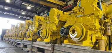
Industrial Engine
Custom cylinder head programs for stationary industrial engines — single and multi-cylinder heads in cast and billet aluminum and cast iron for generator sets, pump sets, compressor drive engines, and industrial prime movers. Combustion chamber volume-matched sets for balanced multi-cylinder performance. IATF 16949 OEM production documentation; 2-week monthly blanket releases with dedicated MAZAK capacity; PPAP Level 3 Cpk ≥1.67 qualification. Full casting procurement program (CNCPioneer-procured A356 or LM25 castings) or customer-supplied rough casting machining programs.
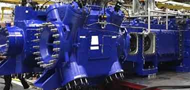
Reciprocating Compressor
Compressor cylinder head supply for natural gas, air, chemical, and hydrogen compression equipment — from low-pressure two-stage air compressor heads through ultra-high-pressure (400+ bar) hydrogen compressor cylinder heads in 316L and 17-4PH H900. Full pressure-containing wall thickness analysis at DFM review. O-ring and metal seal groove machining for high-pressure programs. Material certificates per pressure equipment requirements; 100% LPT on pressure-containing bores for hydrogen service programs. Single and double-acting configurations with 5-axis internal gas passage machining.

Marine Propulsion Equipment
Marine diesel and gas engine cylinder heads in marine-grade aluminum alloys and ductile iron — Bureau Veritas, DNV, Lloyd's Register, and ABS classification society documentation; seawater corrosion protection programs (Type III hard anodize on aluminum heads; electroless nickel on internal coolant passages); precision valve seat and guide machining for long-interval 4,000–8,000 hour TBO marine engine service requirements. Large bore marine heads Ø200–Ø400mm bore machined on MAZAK VARIAXIS 5-axis platforms. Epoxy cavity coating on internal seawater cooling passages for corrosion protection.
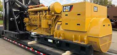
Generator Set
OEM custom cylinder head supply for diesel and gas generator sets at 10,000–500,000 annual unit volumes. Valve seat insert installation and three-angle seat angle machining included. Ignition system feature machining (spark plug threads, prechamber bores, glow plug threads) per generator set engine specification. Injector sleeve pressed-in and bored to final concentricity at CNCPioneer — ±0.003mm concentricity to combustion chamber center. IATF 16949 PPAP Level 3 production. Thread inserts installed in aluminum cylinder heads for repeated torque cycling without thread wear accumulation.
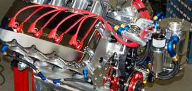
Performance and Motorsport Engine
Custom CNC cylinder head programs for racing engine development — billet 7075-T6 or 2024-T4 construction; chamber volume matched ±0.3cc; precision 5-axis port CNC machining for maximum flow coefficient; five-angle valve seat programs; titanium option for minimum mass. Ra 0.2μm electropolished combustion chamber for reduced carbon deposit nucleation. Same-day DFM response for racing program timelines. Design iteration rapid turnaround: 7–10 days from approved drawing to machined cylinder head enables two design-test cycles per month for active engine development programs.

Agricultural
Agricultural and construction equipment cylinder heads for off-highway diesel engines — ductile iron and aluminum heads with dust ingestion-resistant port geometry; high-cycle valve seat programs for extended field service without seat recession. Hydraulic and pneumatic cylinder head programs for mobile and industrial equipment OEMs — rod seal gland bore ±0.002mm; port threads per SAE/JIC/BSPP specification; tie rod hole patterns ±0.010mm true position; IATF 16949 OEM production with monthly blanket releases. Specialty programs: historic engine reproduction cylinder heads — reverse engineering from original samples by CMM scanning; material matched to original specification.
CNC Cylinder Head Machining
Process and Capabilities
CNCPioneer's cylinder head machining sequence covers the complete 12–25 operation program from raw casting or billet blank through finished cylinder head: deck surface milling, combustion chamber CNC, valve seat and guide boring, coolant passage machining, rocker arm and camshaft bore machining, and all thread features — on MAZAK mill-turn centers, MAZAK VARIAXIS 5-axis platforms, and 78+ Swiss CNC lathes in coordinated single-datum programs that maintain all geometric relationships between critical features.
24-Hour Cylinder Head DFM and Engineering Review
Deck surface flatness achievability for material and head size. Combustion chamber CNC accessibility for designed chamber shape (hemispherical, pent-roof, bathtub, wedge — all 5-axis simultaneous accessible). Valve seat-to-guide concentricity approach (single-setup pilot tooling vs. machined-fixture piloting for complex multi-valve configurations). Minimum wall thickness adequacy for cooling passage positions relative to combustion chamber and deck zone. Head bolt pattern analysis for sealing load distribution across combustion chamber perimeter. Material selection for temperature, pressure, and corrosion environment — billet vs. cast routing per volume and design requirements. Surface treatment specification: Type III hard anodize (with deck masking plan); thermal barrier coating (with post-coating volume re-verification plan); electroless nickel (with plating allowance incorporated in bore dimensions); passivation for stainless. Complete pricing from prototype CNC cylinder head through volume cylinder head in China OEM production.
Deck Surface Milling — 0.010mm/300mm Production Standard
Precision face milling of cylinder head deck surface to 0.010mm/300mm flatness using 200mm diameter face mill with insert height matching (all inserts within ±0.003mm height — mismatched inserts produce periodic undulation at insert spacing frequency). Thermal stabilization: 20-minute pause after rough milling before finish milling eliminating 12–18°C surface temperature gradient that expands the aluminum deck zone and produces waviness after cooling. Single-pass finish milling: no tool retracts during finish pass — eliminating the 0.002–0.005mm step artifact produced at each re-engagement location. Surface finish: Ra 0.8–1.6μm for MLS (multi-layer steel) head gaskets; Ra 1.6–3.2μm cross-hatch for composite head gaskets — feed rate and nose radius matched to achieve specified Ra. Post-machining CMM 25-point grid verification on every cylinder head deck surface with maximum deviation from least-squares reference plane reported before release. Deck surface squareness to cylinder bore axis: 0.010mm/100mm verified by CMM.
Valve Seat and Guide Bore Machining — ±0.003mm Concentricity
Valve guide bore finish: precision reaming to ±0.003mm diameter (Ø7.000–7.020mm standard for 7mm valve stem); bore straightness ±0.005mm/100mm; Ra 0.8–1.2μm for correct oil film in stem-guide clearance — verified by air gauge on every bore. Guide press fit in head bore: H7/n6 or H7/p6 interference fit ±0.003mm. Valve seat insert bore: boring to ±0.002mm for interference fit; perpendicularity to guide bore 0.005mm; depth ±0.050mm for correct insert protrusion. After seat insert installation: three-angle seat cut (top cut, seat cut, bottom cut) using guide-bore-piloted tooling — seat cutter pilots in finished guide bore, mechanically centering on guide bore axis regardless of CNC thermal drift or fixture settling. Seat angle ±0.25°; seat diameter ±0.050mm; seat width ±0.100mm around circumference. Seat-to-guide TIR verified by dial indicator on every valve position every cylinder head — ±0.003mm TIR by mechanical constraint. Three-angle standard; five-angle and narrow-band (0.8–1.2mm) for racing programs.
Combustion Chamber 5-Axis CNC and Volume Matching
5-axis simultaneous machining of hemispherical, pent-roof, bathtub, and wedge combustion chamber forms from customer CAD surface model. Surface finish inside chamber: Ra 1.6μm standard (smooth chamber reduces carbon deposit nucleation); Ra 0.2μm electropolished for racing programs. Squish area: co-planar with deck surface ±0.020mm; width ±0.100mm for designed turbulence intensity. Combustion chamber volume verification: fluid fill method (precision syringe, water-soluble oil, head sealed at deck, fluid introduced through spark plug hole, volume to known datum level measured to ±0.1cc) on every chamber of every cylinder head. Volume tolerance ±0.5cc from design specification; chamber-to-chamber match ±0.5cc within a set (±0.3cc for racing programs). Matched-set documentation: all cylinder volume records compiled per head set confirming every cylinder is within specification. Volume records per chamber per set included in every cylinder head shipment documentation package. Post-TBC volume re-verification available for thermal barrier coating programs (ceramic YSZ 0.1–0.3mm reduces chamber volume by 0.3–1.5cc depending on coating thickness).
Billet Aluminum CNC Cylinder Head Programs
Billet aluminum custom cylinder heads machined from 6061-T6, 7075-T6, or 2024-T4 solid billet — zero porosity risk; tighter wall geometry (±0.050mm wall thickness uniformity vs. ±0.500mm in casting); complete design freedom within 5-axis CNC capability; consistent certified mechanical properties. 5-axis billet machining sequence: billet fixturing with tooling holes establishing all subsequent datums; combustion chamber and port rough machining; valve seat and guide bore rough; water jacket 5-axis simultaneous toolpath through complex internal geometry; deck surface finish milling; combustion chamber 5-axis finish; port finish machining with cross-section area verification at 5 axial stations; valve guide bore precision reaming; valve seat insert bore; all thread features in single setup; external machining; combustion chamber volume fluid fill verification; matched-set documentation. Prototype lead time: 5–8 business days (6061-T6 simple head); 7–10 business days (7075-T6 4-valve pent-roof racing head). Coolant passages drilled as intersecting channels (no casting-core complexity); customer-designed coolant routing accommodated within CNC accessible geometry.
CMM, Volume Records, PPAP Level 3, FAIR AS9102
Certificate of Conformance per cylinder head. CMM dimensional report (Mitutoyo ±0.001mm): deck surface flatness 25-point grid; valve seat positions and concentricity network; head bolt true position (all holes simultaneously); camshaft bore diameters and bore-to-bore concentricity; port face flatness; coolant bore positions; deck squareness to bore axis; overall height. Combustion chamber fluid fill volume records per chamber per set — including matched-set summary showing cylinder-to-cylinder volume range. Dial indicator seat-to-guide TIR records: every valve position of every cylinder head (not sampled). Profilometry: deck surface Ra at three positions; seat surface Ra per cylinder head. Thread gauge records: GO/NO-GO all critical threads (spark plug, injector, head bolts, sensor ports). Material certificates with lot traceability. Surface treatment certifications. PPAP Level 3 Cpk ≥1.67 for OEM programs (deck flatness, valve seat TIR, combustion chamber volume as IATF special characteristics). FAIR (First Article Inspection Report) per AS9102 for aerospace and defense engine programs. Records retained 20 years.
Materials for
Custom Cylinder Heads
Custom cylinder head material selection is governed by operating temperature, combustion pressure, thermal conductivity requirement, corrosion environment, and weight-per-strength priority. A356-T6 cast aluminum dominates standard industrial engine programs for its combination of castability, weight, and thermal conductivity. 7075-T6 billet provides 2.4x higher yield strength for thin-wall racing heads at reduced mass. Gray cast iron provides superior wear resistance for heavy-duty industrial and diesel programs. Stainless steel and nickel alloys address corrosive compressor service.
A356-T6 and LM25 Cast Aluminum
A356-T6: Si 6.5–7.5%, Mg 0.25–0.45%; yield strength 207 MPa; thermal conductivity 155 W/m·K — the best combination of castability, weight, and heat extraction from combustion chamber zones for standard industrial engine cylinder heads. T6 temper (solution treat + age): 70–90 HRB hardness verified incoming at CNCPioneer. Excellent sand casting characteristics allowing complex coolant passage cores, integral valve spring seat bosses, and internal feature geometry not accessible in billet machining programs. Weldable (post-machine repair of minor porosity if located outside critical zones). LM25 (UK/EU equivalent): Si 6.5–7.5%, Mg 0.2–0.6%; similar properties to A356. CNCPioneer procures castings from qualified Chinese foundries with EN 10204 3.1 equivalent composition and hardness certification. Standard for generator set, pump engine, and agricultural equipment cylinder head OEM programs. Type III hard anodize on combustion chamber surfaces available; deck surface masked during anodize.
6061-T6 Billet Aluminum
Yield strength 276 MPa; thermal conductivity 167 W/m·K; machinability excellent — the standard billet material for performance and racing cylinder heads where casting porosity is unacceptable and design freedom from casting constraints is required. Mg 0.8–1.2%, Si 0.4–0.8%, Cu 0.15–0.4% — fully precipitation-hardened T6 condition. Zero porosity vs. A356-T6 casting: eliminates the coolant leakage through cylinder head walls that affects a percentage of even high-quality aluminum castings. Billet wall thickness uniformity ±0.050mm vs. ±0.500mm in casting — enabling minimum wall sections that reduce head mass by 15–20% at equivalent stiffness. Anodizable: Type III hard anodize on combustion chamber surfaces for wear resistance; deck surface masked. Standard for industrial prototype programs (any quantity from 1 piece), performance engine development heads, and custom applications requiring rapid design iteration (5–8 day prototype lead time from solid billet).
7075-T6 and 2024-T4 Billet Aluminum
7075-T6: yield strength 503 MPa — 2.4x higher than A356-T6 for thin-wall billet cylinder heads enabling minimum wall sections at target stiffness, reducing head mass by 15–25% vs. cast aluminum heads while maintaining structural adequacy. Zn 5.1–6.1%, Mg 2.1–2.9%, Cu 1.2–2.0%. Not weldable (susceptible to hot cracking); not as corrosion-resistant as 6061. For maximum performance-per-gram in racing and aerospace engine programs. 2024-T4: yield strength 324 MPa; high fatigue strength — fatigue endurance 138 MPa at 5x10^8 cycles; for aerospace and high-cycle racing cylinder head programs where fatigue resistance at valve spring load cycling is the binding material constraint rather than static strength. Cu 3.8–4.9%, Mg 1.2–1.8%. Not anodizable with Type III hard anodize due to copper content — alternative: dichromate or chromate conversion coating for corrosion protection. Both grades machined on MAZAK VARIAXIS 5-axis platforms at CNCPioneer; prototype 7–10 business days from solid billet.
EN-GJL-250 Gray Cast Iron
UTS 250 MPa; thermal conductivity 50 W/m·K; superior wear resistance at valve seat and guide bore interfaces from graphite flake microstructure — the dominant material for heavy-duty diesel and gas industrial engine cylinder heads where aluminum hardness produces valve seat recession under high-temperature, high-load valve seating cycles. Self-damping from graphite microstructure reduces combustion noise transmission through cylinder head body. Brinell hardness 150–220 HB verified incoming; castings pressure-tested at 3 bar, 5 minutes, zero leakage before machining investment. Valve seat recession performance: EN-GJL-250 is compatible with dry valve seat operation (natural gas, LPG, hydrogen combustion) without seat insert recession that affects aluminum heads in these fuel applications. Maximum service temperature approximately 300°C deck surface (vs. 200°C for A356-T6 before strength degradation). Cast iron cylinder heads: customer-supplied rough castings or CNCPioneer-procured from qualified Chinese foundries with material certification. Phosphate treatment plus assembly lube as standard post-machining treatment for corrosion protection during storage and shipping.
EN-GJS-500 Ductile Iron and 4130/42CrMo4 Steel
EN-GJS-500 (Ductile Iron): UTS 500 MPa; elongation 7% minimum — substantially stronger than gray iron EN-GJL-250 with ductile fracture mode rather than brittle. For high-pressure reciprocating compressor cylinder heads to 300 bar where gray iron's brittle behavior at stress concentrations (valve pocket bores, gas passage intersections) is unacceptable. Hardness 180–280 HB incoming verified. 4130 / 42CrMo4: yield strength 655 MPa in normalized+tempered condition; for ultra-high-pressure compressor cylinder heads (100–700 bar) where ductile iron pressure-containing wall thickness is excessive. Cr 0.8–1.1%, Mo 0.15–0.25%. Wall thickness adequacy calculation at CNCPioneer DFM review against design pressure times 4x safety factor minimum. NACE MR0175 hardness max 22 HRC for H2S-service compressor cylinder heads. Incoming Brinell hardness verification per lot — confirming heat treatment condition compliance before machining. O-ring and backup ring seal groove ±0.015mm width and depth for reliable sealing at design pressure. Phosphate plus rust preventive for carbon steel heads during transit.
316L Stainless Steel
C max 0.030%; Cr 16–18%; Ni 10–14%; Mo 2–3%; PREN approximately 24.3; temperature range -196 through +870 degrees C. For compressor cylinder heads in corrosive gas service (H2S/CO2 mixtures, chlorinated gas, acid gas) where carbon steel or cast iron would corrode from the process fluid; marine engine cylinder heads where seawater contact with internal passages is unavoidable; chemical compressor cylinder heads in pharmaceutical and chemical plant service where process fluid compatibility with stainless is required by specification. Low carbon (316L) prevents sensitization in weld-repaired compressor cylinder heads. NACE MR0175 hardness compliance at 200 HB maximum for H2S service. Passivation ASTM A967 standard post-machining treatment. Machined on MAZAK mill-turn with stainless-specific tooling and coolant parameters. Electroless nickel on internal coolant passages for additional corrosion protection in marine seawater cooling applications.
17-4PH H900 Stainless Steel
Yield strength 1,310 MPa (H900 age-hardened condition); UTS 1,379 MPa; hardness 44–47 HRC; corrosion resistance: superior to 304 stainless in atmospheric and mild chemical environments from Cr 15–17.5% content. The material for ultra-high-pressure (400+ bar) compressor cylinder heads where 316L's 170 MPa yield strength requires wall sections so thick they are structurally or economically impractical. H900 condition (900 degree F / 482 degree C age hardening): achieved after machining at CNCPioneer; aged at 482 degrees C for 1 hour produces peak hardness. Pressure-containing wall thickness calculation at CNCPioneer DFM review against design pressure x 4 safety factor. Seal groove machined to ±0.015mm; valve pocket bore concentricity to cylinder bore axis ±0.005mm. Ra 0.4μm on all pressure-containing bore surfaces for correct O-ring contact and fatigue resistance. 100% LPT (liquid penetrant testing) on all pressure-containing bores before assembly. Passivation ASTM A967 post-machining. EN 10204 3.1 equivalent material certification per lot.
Ti-6Al-4V Titanium and Inconel 625
Ti-6Al-4V: yield strength 950 MPa; density 4.43 g/cm3 — 60% of aluminum alloy density at 3.4x the yield strength; non-magnetic; outstanding fatigue resistance. For aerospace engine cylinder heads where minimum mass governs; ultra-lightweight racing cylinder heads in sanctioned classes where titanium is permitted; specialized hydraulic cylinder heads in MRI-compatible equipment (non-magnetic per ur approximately 1.0005). Machined from ASTM B381 Grade 5 bar with dedicated carbide tooling, controlled cutting parameters, and through-coolant. DLC coating on valve seat bore contact surfaces for wear resistance. Prototype 10–14 business days from titanium bar stock. Inconel 625 (UNS N06625): yield strength 480 MPa; Cr 20–23%, Mo 8–10%; excellent high-temperature strength retention to 982 degrees C; for extreme temperature compressor cylinder heads in exhaust gas compression, hot gas recirculation, and hydrogen service at elevated temperature. Machined on MAZAK with nickel alloy-specific tooling management protocols. Passivation ASTM A967 standard post-machining. EN 10204 3.1 material certification standard.
Surface Treatments for
Custom Cylinder Heads
Custom cylinder head surface treatments serve four engineering functions: wear resistance on aluminum combustion chamber surfaces and valve areas (Type III hard anodize); thermal barrier for reducing combustion heat transfer to coolant (ceramic TBC); corrosion protection on internal coolant passages of marine and chemical service heads (electroless nickel); and valve guide bore wear protection in dry-combustion fuel service (hard chrome). Treatment masking of critical sealing surfaces and valve guide bores is incorporated into the treatment plan at DFM stage — post-treatment precision boring restores guide bore and seat insert bore dimensions where treatment buildup affects interference fit dimensions.
Type III Hard Anodize — MIL-A-8625 (Aluminum Cylinder Heads)
Wear-resistant surface for aluminum engine cylinder head combustion chamber surfaces, valve seat area, and external surfaces — HV 400+ hardness significantly improving combustion chamber surface durability against carbon deposit and valve impact erosion. Black hard anodize on combustion chamber surfaces reduces thermal radiation from combustion, lowering local surface temperature and contributing to heat flux reduction into the coolant jacket. Anodize dimensional growth on deck surface is 0.015–0.050mm per side — this is the critical masking requirement: the deck surface must be masked during anodize application. CNCPioneer's treatment plan masks the deck surface and all valve seat insert bore and valve guide bore zones before anodize; these surfaces are either not anodized (bare aluminum for gasket seating compliance) or separately hard anodized per engine builder specification with pre-planned dimension allowances. Internal coolant passage anodize available for corrosion protection in marine and chemical service programs. Type II anodize (soft, 0.005–0.015mm) for cosmetic protection on external head body surfaces. MIL-A-8625 Type III certificate per lot shipped with cylinder head documentation package.
Anodize specsThermal Barrier Coating — Ceramic YSZ (Combustion Chamber)
Yttria-stabilized zirconia (YSZ) thermal barrier coating on combustion chamber surfaces — 0.1–0.3mm ceramic coating with thermal conductivity approximately 2.5 W/m·K (vs. 155 W/m·K for A356 aluminum) reducing heat transfer from combustion gases into cylinder head material. Applications: diesel and industrial gas engines where reducing cooling load improves thermal efficiency; race engines where reducing combustion heat loss to coolant improves BMEP (brake mean effective pressure); performance engines converting to alternative fuel with higher combustion temperatures. Applied by plasma spray after precision CNC machining of the combustion chamber to final dimensions. Critical post-coating step: combustion chamber volume re-verified by fluid fill after coating application — ceramic coating reduces chamber volume by 0.3–1.5cc depending on coating thickness per surface. Volume must be confirmed within ±0.5cc specification post-coating before cylinder head is released. Coating adhesion: 25 MPa minimum bond strength per ASTM C633; thermal cycling test per ASTM B117 salt spray for corrosion resistance of coated zone exterior. TBC certificate per lot including coating thickness measurement records shipped with cylinder head documentation package.
TBC specsElectroless Nickel — MIL-C-26074 (Marine and Chemical Service)
Corrosion protection for aluminum cylinder heads in marine and chemical compressor service — uniform coating on all internal coolant passage surfaces preventing pitting corrosion from seawater contact (marine heads with seawater cooling circuits) or chemical process fluid contact (chemical compressor cylinder heads where coolant contamination with process fluid cannot be excluded). Electroless nickel provides: uniform deposit on complex internal passage geometry (unlike electroplating, which requires line-of-sight electrical contact); hardness HV 450–600 (as-deposited mid-phosphorus type) improving bore surface wear resistance in guide bore areas; and corrosion resistance in neutral to mildly alkaline environments. Plating allowance 0.015–0.030mm per side incorporated in machined bore dimensions before plating: valve seat insert bores and valve guide bores post-plate precision-bored to final specification (valve guide bore to ±0.003mm; seat insert bore to ±0.002mm) after electroless nickel application. Plating thickness 25–50μm on external surfaces; 15–25μm on deep internal coolant passage surfaces. Adhesion test per ASTM B571. MIL-C-26074 certificate per lot shipped with cylinder head documentation.
EN plating specsHard Chrome — Valve Guide Bores (Natural Gas and LPG Service)
Wear-resistant hard chrome coating for cylinder head valve guide bores and seat areas in high-wear dry-combustion fuel applications — particularly natural gas and LPG engine cylinder heads where fuel-borne lubricants are absent compared to diesel and gasoline fuels, accelerating dry-combustion valve guide wear significantly beyond rates in fueled-lubrication engine programs. Hard chrome properties: HV 850–1,050; excellent wear resistance; low coefficient of friction. Chrome-plated valve guide bores: guide bore machined 0.010–0.025mm undersize before chrome application; post-chrome bore honed to final Ra 0.8μm and ±0.003mm diameter specification. Seat area hard chrome for gas engine programs: seat contact zone protected against erosive wear from high-frequency (valve open/close per revolution) dry metal impact. Chrome thickness 0.025–0.050mm verified by eddy current gauge. Note: hard chrome is subject to environmental regulation (hexavalent chromium REACH and RoHS restrictions in EU and California) — trivalent chrome or alternative coating programs available for programs requiring RoHS/REACH compliance. Hard chrome certificate per lot including thickness verification records.
Chrome specsPassivation ASTM A967 and Phosphate Treatment
Passivation per ASTM A967: mandatory for all 316L, 17-4PH H900, and Inconel 625 stainless and nickel alloy cylinder heads — nitric acid or citric acid passivation per Method A or C restores the chromium oxide passive layer at all machined surfaces after machining removes or disrupts the native passive layer. Critical for compressor cylinder heads in corrosive gas service where passive layer integrity determines whether pitting corrosion initiates at machined bore surfaces. Zero dimensional change — valve pocket bores, O-ring grooves, and seal contact surfaces machined to final dimension; passivation does not alter dimensions. Post-passivation copper sulfate test per ASTM A967 Section 8 confirming free iron removal before release. Ferroxyl test where copper sulfate is inconclusive. Passivation certification per lot shipped with EN 10204 3.1 material certificate. Phosphate plus assembly lube (gray iron heads): zinc or manganese phosphate conversion coating (5–10μm) on all gray iron cylinder head exterior machined surfaces — phosphate film provides corrosion protection during storage and shipping; facilitates engine oil lubrication retention at valve guide bores and coolant passage inner surfaces during first-start break-in; removed by solvent degreasing before engine assembly or customer's coating application.
Passivation specsDLC and PVD Coatings — Racing and Low-Friction Programs
Diamond-like carbon (DLC) and PVD (physical vapor deposition) coatings for racing and performance cylinder head valve guide bores and combustion chamber surfaces in programs requiring minimum friction, maximum wear resistance, and freedom from hexavalent chrome environmental restrictions. DLC coating (a-C:H type): HV 1,500–3,000; coefficient of friction approximately 0.05–0.10 in boundary lubrication (vs. 0.15–0.20 for uncoated aluminum or gray iron); excellent wear resistance for valve stem contact surface in guide bore. Coating thickness: 1–4μm PVD process — negligible dimensional change requiring no pre-coat bore machining allowance for guide bore programs. Temperature limitation: a-C:H DLC decomposes above approximately 300–400 degrees C continuous — limiting application to valve guide bore zones (guide bore ambient temperature: 80–180 degrees C in operation) rather than combustion chamber surfaces (peak temperature 300–600 degrees C). TiN (titanium nitride) PVD: HV 2,000–2,500; gold colored; for seat insert bore surfaces and valve train contact zones where DLC temperature limit would be exceeded. Both coatings applied after precision machining of all dimensional-critical features; post-coat dimensional verification confirms no distortion from PVD deposition temperature (180–200 degrees C). Coating certificate including thickness and adhesion records per lot.
DLC/PVD specsAll surface treatments on custom cylinder head programs — Type III hard anodize MIL-A-8625, thermal barrier ceramic YSZ coating, electroless nickel MIL-C-26074, hard chrome, passivation ASTM A967, phosphate treatment, DLC and PVD coatings — are coordinated within CNCPioneer's cylinder head machining program with appropriate masking plans for deck surface, valve guide bores, and seat insert bores. Post-treatment precision boring restores valve guide bore and seat insert bore dimensions where treatment buildup affects interference fit specifications. Combustion chamber volume is re-verified by fluid fill after thermal barrier coating application to confirm volume is within ±0.5cc post-coating.
Quality Assurance for
Custom Cylinder Head Programs
Custom cylinder head quality assurance addresses the three performance-critical dimensional systems: deck surface flatness for head gasket sealing (0.010mm/300mm CMM verified on every head), combustion chamber volume for compression ratio balance (fluid fill verified on every chamber, matched-set documented), and valve seat-to-guide concentricity for full-circumference valve contact (dial TIR verified on every valve position of every cylinder head) — verified by Mitutoyo CMM, precision fluid fill apparatus, and dial indicator TIR check before any cylinder head is released.
Engineering DFM Review and Cylinder Head Configuration Review
24-hour DFM on every custom cylinder head inquiry: deck surface flatness achievability for material and head size — MLS (multi-layer steel) gasket programs require 0.010mm/300mm; composite gasket programs may accept 0.020mm; metal O-ring and C-ring compressor programs require 0.005–0.008mm. Combustion chamber CNC accessibility for designed chamber shape (hemispherical, pent-roof, bathtub, wedge — all 5-axis simultaneous accessible from MAZAK VARIAXIS; shallow wedge accessible from 3-axis mill-turn). Valve seat-to-guide concentricity approach: single-setup pilot tooling standard for multi-valve heads; machined-fixture piloting for complex multi-angle multi-valve configurations. Minimum wall thickness adequacy for cooling passage positions relative to combustion chamber and deck zone — CNCPioneer flags thin-wall conditions (below 3.0mm in aluminum, 4.0mm in cast iron) for designer review before machining. Head bolt pattern analysis for sealing load distribution around combustion chamber perimeter — unbalanced bolt patterns produce non-uniform gasket load that simulates flatness error. Material selection: billet vs. cast routing, stainless vs. carbon steel for compressor programs. Surface treatment masking plan for treatments that would alter deck surface, valve guide, or seat insert bore dimensions.
Material Incoming Inspection
SII XRF composition verification on every billet and casting lot (16 elements simultaneously — confirms A356 vs. LM25 vs. 6061 vs. 7075; gray iron vs. ductile iron; 316L vs. 304 vs. 17-4PH) before machining release. Hardness verification per lot: T6 aluminum castings (70–90 HRB); 7075-T6 billet (84–88 HRB); gray iron EN-GJL-250 (150–220 HB); ductile iron EN-GJS-500 (180–280 HB); 17-4PH H900 (44–47 HRC confirmed before machining, after aging). Visual inspection of castings for surface defects at critical machining zones: cracks, cold shuts, misruns, or heavy porosity at deck zone, combustion chamber walls, or valve seat areas — any of these disqualify the casting before machining investment. Pressure test on pre-cored castings with internal coolant passages: hydrostatic pressure at 3 bar, 5 minutes, zero leakage — verifying casting soundness before machining begins. For castings with casting porosity found post-machine at non-critical zones: CNCPioneer reviews with customer whether repair (TIG weld + re-machine) or replacement is appropriate before proceeding.
In-Process Controls — Adaptive Deck Flatness and First-Off CMM
In-process deck surface flatness measurement by CNC contact probe mounted on machine spindle during facing operation — adaptive correction applied if measured flatness deviation exceeds 0.008mm at any probe station during the facing pass. This in-process correction prevents flatness non-conformance from accumulating to the point where re-facing would consume additional machining stock. Thermal stabilization protocol documented in process traveler: minimum 20-minute hold after rough deck milling before finish milling; ambient temperature monitoring confirms deck zone temperature within ±2 degrees C of ambient before finish milling begins. First-off CMM on deck surface flatness, valve seat positions, bolt hole true position, and combustion chamber preliminary volume probe before batch machining of any multi-piece program. Single-setup valve seat and guide bore machining verified by first-off dial TIR check — if first-off TIR exceeds 0.005mm, tooling registration is verified and corrected before batch valve seat boring begins. Combustion chamber volume fluid fill measurement on first article of every new program before proceeding — confirms that the CNC chamber program achieves target volume ±0.5cc before the full set is machined.
Final Inspection — CMM, Fluid Fill, Dial TIR, Profilometry
Mitutoyo CMM (±0.001mm): deck surface flatness (25-point minimum measurement grid; maximum deviation from least-squares reference plane reported per head); deck squareness to cylinder bore axis (0.010mm/100mm); all valve seat positions in network (concentricity and position relative to bore axis datum); head bolt hole true position (all holes simultaneously in one CMM program — not individual holes that miss angular network errors); camshaft bearing bore diameters and bore-to-bore concentricity (OHC heads); port face flatness (intake and exhaust manifold mating faces); coolant bore positions; spark plug thread positions; overall head height from deck to specified datum. Combustion chamber fluid fill: every chamber of every cylinder head — precision syringe measurement to ±0.1cc; records per chamber per head; matched-set summary showing all cylinder volumes within ±0.5cc. Dial indicator seat-to-guide TIR: every valve position of every cylinder head — probe registers in finished seat groove with dial stem passing through guide bore; TIR directly measures seat-to-guide runout; ±0.003mm TIR = ±0.006mm concentricity maximum. Thread gauges GO/NO-GO on all critical threads: spark plug, injector, head bolts, temperature sensor ports. Profilometry: deck surface Ra at three positions; seat surface Ra per cylinder head. Visual: burrs at valve guide bore exits; combustion chamber edges clean; valve seat contact band uniformity.
Combustion Chamber Volume Verification — Every Chamber, Every Head
Combustion chamber volume verification by fluid fill method is performed on every chamber of every cylinder head produced by CNCPioneer — not on a sample basis, not on first article only. The fluid fill method: head inverted on a level fixture; combustion chamber opening sealed at deck surface using a clear acrylic plate with precision hole at spark plug thread location; water-soluble oil introduced through spark plug hole using a precision calibrated syringe reading to 0.1cc; oil volume recorded when fluid level reaches the precisely known reference datum (bottom edge of spark plug hole thread — the same reference for every head). Volume record: per chamber for single-cylinder heads; per cylinder for multi-cylinder heads with matched-set compilation confirming range within ±0.5cc (±0.3cc for racing matched-set programs). Post-TBC volume re-verification: for cylinder heads with thermal barrier coating applied post-machining, fluid fill is repeated after coating application — ceramic 0.1–0.3mm coating reduces chamber volume by 0.3–1.5cc depending on coating thickness per surface; this post-coating volume determines actual compression ratio and must be verified within ±0.5cc specification before release. Volume records per cylinder per set are included in the cylinder head shipment documentation package for customer engine assembly record and compliance documentation.
Documentation Package
Certificate of Conformance per cylinder head or per matched set. Mitutoyo CMM dimensional report: deck flatness 25-point grid, deck squareness, valve seat positions and concentricity network, head bolt true position (all holes simultaneously), camshaft bore diameters and concentricity, port face flatness, coolant bore positions, spark plug thread positions, overall height — all measured vs. drawing tolerances in tabular format per serial number. Combustion chamber fluid fill volume records: per chamber per head; matched-set summary for multi-cylinder programs showing cylinder-to-cylinder range and maximum deviation. Dial indicator seat-to-guide TIR records: every valve position of every cylinder head — all values listed per valve per head. Profilometry: deck surface Ra at three positions; seat surface Ra. Thread gauge records: GO/NO-GO all critical threads per cylinder head. Material certificates with lot traceability (billet bar or casting heat number to machining lot to cylinder head serial number). Surface treatment certifications (Type III hard anodize MIL-A-8625; electroless nickel MIL-C-26074; hard chrome thickness; TBC coating records; passivation ASTM A967 test result). PPAP Level 3 Cpk ≥1.67 for OEM programs on deck flatness, seat TIR, and combustion chamber volume as IATF special characteristics. FAIR per AS9102 for aerospace and defense engine programs. Records retained 20 years.
IATF 16949 Quality System for
Custom Cylinder Head Programs
CNCPioneer's IATF 16949 and AS9100D certified quality system addresses four quality disciplines specific to precision cylinder heads: 100% CMM deck flatness on every head (not sampled) at the 0.010mm/300mm specification that head gasket sealing requires, 100% combustion chamber volume fluid fill verification on every chamber for matched-set compression ratio balance, 100% valve seat-to-guide TIR on every valve position for full-circumference valve sealing, and PPAP Level 3 Cpk ≥1.67 qualification bridging from first article through OEM volume supply programs.
100% CMM Deck Flatness — Every Cylinder Head
Every custom cylinder head — every industrial engine head, every compressor head, every racing head — receives 100% CMM verification of deck surface flatness by 25-point minimum measurement grid with maximum deviation from least-squares reference plane reported per head serial number. 100% CMM rather than sampling is necessary at the 0.010mm/300mm specification bandwidth because the consequence of a non-conforming deck surface reaching the engine builder is a blown head gasket on first engine start — the non-conformance is only detected after engine assembly cost has been committed. The 25-point measurement grid covers the deck zone with adequate density to detect the bowl-and-saddle waviness pattern from thermal gradient effects and the edge-to-center height difference from face mill insert height variation — both modes that a sparse measurement pattern would miss. CMM verification is at ambient temperature (not at machining temperature), confirming the thermal stabilization protocol was effective. CMM report includes point cloud data and contour map of deck flatness per head serial number, archived and shipped as PDF with every cylinder head.
- 100% CMM 25-point deck flatness on every cylinder head
- CMM at ambient temperature — confirms thermal stabilization
- Point cloud and contour map per serial number in shipment docs
100% Combustion Chamber Volume — Fluid Fill Every Chamber
Every combustion chamber of every cylinder head undergoes fluid fill volume measurement — not sampled, not inferred from CNC program coordinates. The fluid fill method provides a direct physical measurement of the as-machined combustion chamber volume that includes all dimensional contributions: the machined chamber floor and wall geometry, the deck surface height contribution, the squish band geometry, and any residual machining tool deflection effects that would not be captured by coordinate-based volume calculation from CMM point data. Volume measurement precision: ±0.1cc per syringe reading (typical total volume precision ±0.15cc per measurement) — adequate to confirm ±0.5cc tolerance with 3x safety margin. Matched-set documentation for multi-cylinder programs: all cylinder volume records per set are compiled in a table showing individual cylinder volumes and the maximum deviation within the set (specification: ±0.5cc range). This matched-set documentation is the quality record that the engine builder uses to confirm balanced compression ratio distribution before engine assembly — and that the engine performance dyno sheet retrospectively validates against cylinder power balance data. For post-TBC programs: volume re-measurement after ceramic coating application is mandatory; coating-adjusted volume per chamber documented and compared to design specification and pre-coating volume.
- Fluid fill on every chamber of every cylinder head — not sampled
- Precision ±0.1cc syringe measurement to ±0.15cc total precision
- Matched-set documentation: all cylinder volumes per set compiled
100% Valve Seat TIR — Dial Indicator Every Valve Position
Every valve position of every cylinder head receives dial indicator seat-to-guide TIR (total indicator runout) verification: a dial indicator probe registers in the finished valve seat groove while the dial stem passes through the valve guide bore; the cylinder head is rotated through 360° on the guide bore axis; TIR reading directly measures seat-to-guide concentricity runout. This method is preferred over CMM seat-and-guide position measurement for two reasons: it is a direct functional simulation of the valve's actual alignment (the guide bore axis is the rotation datum; the seat contact band is the measured surface — exactly the geometric relationship that governs valve contact uniformity in service); and it catches any concentricity error from seat cutter wear, pilot clearance growth, or re-chucking error that coordinate-based CMM inspection would have to infer from point data. TIR specification: ±0.003mm TIR (= ±0.006mm total runout maximum) for standard cylinder head programs; ±0.002mm TIR (= ±0.004mm) for precision industrial and racing programs. Any valve position exceeding TIR specification: pilot tooling registered in guide bore, seat angle re-cut in single-setup to restore concentricity; re-measured by dial TIR before release. TIR records per valve position per cylinder head archived and shipped with documentation.
- Dial TIR on every valve position of every cylinder head
- Direct functional measurement — simulates actual valve alignment
- TIR records per valve per head in shipment documentation
PPAP Level 3 / FAIR AS9102 — OEM and Aerospace Programs
PPAP Level 3 qualification for custom cylinder head OEM programs: design records (drawing and CAD model revision traceability); process flow diagram (complete machining sequence from material receiving through surface treatment through final inspection and documentation); PFMEA (failure mode and effects analysis identifying deck flatness non-conformance, seat TIR non-conformance, and combustion chamber volume non-conformance as the three highest-consequence failure modes); control plan specifying measurement frequency and method for each special characteristic; MSA Gage R&R on CMM probe system (deck flatness and bolt circle), fluid fill apparatus (combustion chamber volume), and dial indicator (seat TIR) — all at ≤10% gauge variation of tolerance; initial process capability studies with Cpk ≥1.67 on deck flatness, seat-to-guide TIR, combustion chamber volume, and head bolt true position as IATF 16949 special characteristics; and part submission warrant (PSW). PPAP qualification timeline: 6–8 weeks from pilot production completeness through customer approval. FAIR (First Article Inspection Report) per AS9102 for aerospace and defense engine programs: complete inspection of 100% of drawing characteristics per AS9102 requirements; balloon drawing cross-referenced to inspection results; material certification; surface treatment certification; all process NCRs documented and dispositioned. Quality metrics: 99% qualification rate; 100% on-time delivery on established OEM programs.
- PPAP Level 3 Cpk ≥1.67 for cylinder head OEM programs
- FAIR per AS9102 for aerospace and defense engine programs
- 99% qualification rate · 100% on-time delivery
Custom Cylinder Head FAQ
Common questions from industrial engine manufacturers, compressor OEMs, marine equipment builders, motorsport engine developers, and hydraulic equipment producers about cylinder head deck flatness specifications, valve seat concentricity methods, billet vs. cast material selection, and cylinder head in China production economics and lead times.
Deck surface flatness specification is determined by the head gasket type and its seating compliance — the gasket's ability to compensate for small deck surface irregularities through elastic or plastic deformation during initial bolt torque. Composite fiber gaskets (the traditional multi-layer fiber-and-steel-bead type): plus or minus 0.040–0.060mm/300mm — these gaskets have significant seating compliance from the soft fiber-reinforced body, tolerating moderate deck irregularity. Multi-layer steel (MLS) gaskets: plus or minus 0.010–0.020mm/300mm — MLS gaskets have minimal compliance because the thin steel layers can only conform to very small waviness; above 0.020mm flatness deviation, MLS gaskets develop high and low zones that produce cyclic gasket stress variation under combustion loading, initiating fatigue delamination of the steel layers at the stress concentration zones. Metal O-ring and C-ring gaskets (high-pressure industrial and compressor heads): plus or minus 0.005–0.008mm — these gaskets rely entirely on deck surface geometry for sealing; no gasket compliance supplements deck imperfection. CNCPioneer achieves 0.010mm/300mm deck surface flatness in production through four compounded process disciplines. First, face mill insert height matching: all inserts at the same height within plus or minus 0.003mm — mismatched inserts produce periodic undulation at the insert spacing frequency. Second, thermal stabilization: rough face milling raises the aluminum head's surface temperature approximately 12–18 degrees C, expanding the deck zone; CNCPioneer's programs include a 20-minute thermal stabilization pause after rough milling before finish milling — wait for the temperature gradient to dissipate before finish milling begins. Third, single-pass finish: finishing in a single continuous pass without tool retracts eliminates the step artifact produced when a tool lifts and re-engages (0.002–0.005mm height discontinuities at each re-engagement location). Fourth, CMM verification: every cylinder head deck surface is verified by 25-point CMM measurement at ambient temperature before release — confirming that the thermal stabilization protocol was effective and that the face mill inserts remain within height specification.
The critical importance of valve seat concentricity to guide bore is understood through valve contact mechanics. When a poppet valve closes against its seat, the valve disc contacts the seat along a circular contact band. For this band to have uniform contact pressure around the full 360 degrees — which is required for combustion gas sealing and for even valve-face cooling from seat contact — the seat's center must be exactly on the valve stem axis, which is defined by the valve guide bore axis. If the seat center is offset from the guide bore by 0.010mm, the valve face contacts the seat heavily on one side and lightly or not at all on the opposite side — creating asymmetric contact that seals poorly on the light-contact side and over-stresses the seat insert material on the heavy-contact side. In service, the light-contact side allows hot combustion gas to leak through the seat at each valve closing event, eroding the seat and valve face by thermal and mechanical mechanisms simultaneously — producing valve burning and seat recession that destroy engine sealing in a fraction of the designed valve seat service life. CNCPioneer achieves plus or minus 0.003mm concentricity through single-setup seat-and-guide boring using a purpose-built pilot tooling system: after the valve guide bore is finish-reamed to plus or minus 0.003mm diameter in the primary machine setup, a seat cutting tool mounted on a precision pilot that registers in the finished guide bore is used to bore the seat insert counterbore. The pilot in the guide bore mechanically centers the seat cutter on the guide bore axis — concentricity is achieved by tooling registration, not by CNC positioning accuracy, which means the concentricity is maintained regardless of any thermal drift, fixture settling, or position variation in the machine during the seat boring operation. After seat insert installation and seat angle cutting (also using guide-bore-piloted tooling), the finished seat form is verified by dial indicator: the tip registers in the finished seat groove while the dial stem passes through the valve guide bore — TIR reading directly measures seat-to-guide runout. Plus or minus 0.003mm concentricity produces TIR of 0.006mm maximum, within the 0.010mm maximum that engine valve manufacturers specify for their valve sealing performance guarantees.
The choice between billet and cast aluminum for a custom cylinder head program involves four trade-off dimensions — cost, design freedom, material properties, and lead time — and the correct choice depends on which dimension is the binding constraint. Cast aluminum cylinder heads (A356-T6 or equivalent): the casting process produces near-net-shape geometry with hollow internal features (coolant passages, port shapes) formed by sand or die cores during solidification — features that billet machining can only approximate through intersecting drilled or EDM-machined passages. Cast heads have lower material cost (aluminum scrap plus casting labor vs. expensive billet bar) and suit high production volumes where tooling investment amortizes; the minimum order quantity and tooling lead time (pattern/die fabrication: 6–12 weeks, $3,000–$30,000 depending on complexity) make casting non-viable for single prototype or low-volume custom programs. Casting porosity (trapped gas voids in the solidified metal) is an inherent casting limitation — managed by process control (vacuum casting, directional solidification) but not eliminated; porosity at coolant passage walls produces coolant leakage that is undetectable before engine assembly. Billet aluminum cylinder heads (6061-T6, 7075-T6, 2024-T4): machined from solid bar or plate with zero casting porosity risk; coolant passages machined as intersecting drilled channels rather than cast forms (limiting coolant circuit complexity but eliminating porosity risk); higher material cost and machining time than casting for equivalent geometry, but zero tooling investment, 5–10 day prototype lead time, and complete design freedom within 5-axis CNC machining capability. CNCPioneer's recommendation: cast aluminum for high-volume (100+ per year) cylinder heads where complex cooling passages are required and tooling investment is justified; billet aluminum for single prototypes, racing, low-volume industrial engines, and any application requiring absolute coolant passage integrity guarantee. Cast aluminum cylinder heads from customer-provided rough castings: CNCPioneer accepts customer-supplied rough castings and applies the complete precision CNC machining sequence — the cost model that allows casting economy (customer-controlled casting program) with CNCPioneer's precision machining quality for the dimensional-critical features.
Prototype lead times at CNCPioneer's custom cylinder head factory: billet 6061-T6 single-cylinder head with 2-valve combustion chamber — 5–7 business days; billet 7075-T6 4-valve pent-roof racing cylinder head — 7–10 business days; cast aluminum supplied by customer plus machined — 7–10 business days (machining time only; casting procurement separately); cast aluminum procured by CNCPioneer plus machined — 12–18 business days (includes casting foundry schedule); gray iron casting machined — 8–12 days; stainless compressor cylinder head — 8–12 days; high-pressure 17-4PH H900 compressor cylinder head — 10–14 days. Combustion chamber volume matched set verification adds 1 business day for fluid fill measurement and set documentation. Hard anodize adds 3 days. Expedite available for 3-day billet aluminum simple single-valve cylinder head on machining-ready designs. Pilot production (25–100 cylinder head sets): 2–3 weeks per batch; SPC accumulation on deck flatness and valve seat TIR beginning. PPAP Level 3: 6–8 weeks from pilot completeness. Volume OEM production: 2-week monthly releases with dedicated MAZAK capacity; 40–70% per-unit cost reduction from prototype depending on volume tier. Economics at representative scale: a billet 6061-T6 4-cylinder 4-valve-per-cylinder performance engine cylinder head set (matched to plus or minus 0.5cc, deck 0.010mm/300mm, valve seat TIR plus or minus 0.003mm, passivated) that costs $2,800 per set from a US performance engine machine shop costs approximately $1,550 at CNCPioneer's prototype — and $580–$720 per set at 500 annual sets in cylinder head in China production. For an industrial engine OEM producing 2,000 engines per year with one 4-cylinder head set per engine, China cylinder head manufacturers savings of $800–$1,200 per set produce $1,600,000–$2,400,000 annual cylinder head BOM cost reduction — transforming engine manufacturing economics while maintaining the dimensional quality that engine performance and service life require.
Get a Quote for Custom Cylinder Head Machining
Upload your custom cylinder head drawings, CAD models (STEP, IGES, SolidWorks, PDF), or engine specifications and receive a free DFM review and competitive quotation within 24 hours — covering deck surface flatness achievability for your material and head size, valve seat concentricity approach for your valve configuration, combustion chamber volume matching methodology, billet versus cast material recommendation, coolant passage accessibility and wall thickness adequacy, head bolt pattern sealing load analysis, surface treatment specification for your operating environment, and complete pricing from prototype CNC cylinder head through volume cylinder head in China OEM production supply.