
Robot Output Shafts
Precision Actuator Shaft Manufacturer
CNCPioneer is a precision robot output shafts specialist and certified China robot output shaft manufacturer delivering custom actuator shaft bodies, hollow shaft cable-routing components, and encoder coupling shaft elements with journal accuracy as tight as ±0.002mm — 66+ MAZAK mill-turn centers and 78+ Swiss CNC lathes for humanoid robot OEMs, collaborative robot manufacturers, and industrial robot builders worldwide since 2011.

What Is a
Robot Output Shaft?
A robot output shaft is the precision-machined rotational component that transmits the actuator's reduced torque from the gearbox output element to the robot's structural link — the shaft that physically couples the kinematic chain's driven mechanism to the limb segment it actuates, while simultaneously providing the bearing journal seats, encoder coupling interface, output flange attachment surface, and, in hollow shaft designs, the through-bore that routes power and signal cables through the joint's rotation axis.
The robot output shaft occupies a uniquely consequential position in actuator architecture because it is the single component where every subsystem intersects: the gearbox connects to it, the output bearing seats on it, the structural link attaches through it, the position encoder reads from it, and the cables pass through it. A 0.005mm journal concentricity error between bearing seats produces misalignment that increases friction and reduces bearing life; a 0.005mm encoder seat runout introduces a once-per-revolution position error that the force controller interprets as mechanism motion and fights with unnecessary control effort.
-
Single-setup MAZAK mill-turn concentricity All robot output shaft journals — front bearing seat, rear bearing seat, encoder seat, output flange register — finish-machined in one chucking from one datum, holding concentricity to ±0.002mm by machine positioning accuracy rather than chuck re-registration uncertainty.
-
Hollow shaft engineering as a design discipline Torsional stiffness analysis, bore coaxiality coordination to ±0.005mm, and wall thickness uniformity verification provided as standard DFM practice for every custom hollow shaft program — preventing wall-breach and cable-wear failures discovered late at prototype testing.
-
Complete actuator torque class coverage Finger joint miniature shafts Ø8–18mm on Swiss CNC through knee and hip high-torque shafts Ø40–120mm on MAZAK heavy-duty turning centers — one qualified manufacturing relationship across the complete robot joint range.
-
40–60% China robot output shaft manufacturer cost advantage IATF 16949 and AS9100D certified robot output shaft machining at 40–60% below equivalent US, European, and Japanese precision turning suppliers at identical journal accuracy and hollow shaft precision — DFM review included without surcharge.

Why CNCPioneer as Your
Robot Output Shaft Manufacturer?
The robot output shaft is the actuator's single point of intersection — every subsystem connects through it. CNCPioneer's single-setup MAZAK mill-turn capability addresses the dimensional disciplines that separate reliable robot output shaft production from shafts that pass individual inspection but fail once assembled: journal concentricity, hollow shaft bore coaxiality, and encoder seat runout.
Single-Setup Concentricity as Standard
Multi-journal concentricity — front bearing journal, rear bearing journal, encoder seat, output flange register — held to ±0.002mm from one datum, one chucking. Multi-setup machining at shops without sub-spindle capability produces shafts whose individual journals pass inspection but whose assembled concentricity exceeds specification.
Hollow Shaft Design Partnership
Torsional stiffness analysis, bore-to-OD coaxiality coordination to ±0.005mm, and wall thickness uniformity verification at ±0.050mm provided as standard DFM practice for every custom hollow shaft program — not an afterthought discovered at prototype testing.
Encoder Seat TIR Verification
Encoder seat total indicator runout treated as a primary quality specification — ≤0.003mm standard, ≤0.002mm high-precision — verified by roundness tester on every lot, with TIR records included in the dimensional documentation package.
MAZAK Mill-Turn & Swiss CNC Dual Platform
MAZAK mill-turn centers handle complex multi-feature bus fittings, hollow shaft bodies, and integrated flange geometry; Swiss CNC lathes produce precision finger and wrist joint miniature shafts at minimum diameter capability — single-source coverage across the complete torque class range.
24-Hour Robot Output Shaft DFM Review
Every inquiry receives comprehensive DFM review within 24 hours: journal concentricity feasibility, hollow shaft wall thickness adequacy, encoder seat concentricity budget, and bearing interference class specification — at no cost, before any machining commitment.
40–60% China Robot Output Shaft Manufacturer Cost
CNCPioneer's China robot output shaft manufacturer cost structure delivers 40–60% cost reduction versus US, European, and Japanese precision turning suppliers — reflecting labor cost and manufacturing efficiency economics, not reduced quality system rigor. DFM review and dimensional documentation are included in pricing.
Robot Output Shaft Types
We Manufacture
CNCPioneer's robot output shaft machining covers the complete range of actuator shaft architectures — solid and hollow shafts across all joint torque classes, harmonic drive and QDD gearbox interfaces, and instrumented sensing shafts — with full dimensional documentation for every production lot.

Solid Robot Output Shafts
Standard integral-flange shafts (output bearing journal ±0.002mm, flange perpendicularity 0.005mm), short stub disc-format shafts for ultra-compact harmonic drive joint packaging, and tapered output shafts (Morse or metric taper, angular accuracy ±0.01°) for joints without through-shaft cable routing requirements.

Miniature Hollow Shafts — Finger & Wrist Joints
Ø10–25mm OD, through-bore Ø4–10mm, wall 2.0–4.0mm — Swiss CNC gun-drilled bore position ±0.020mm over 50–80mm shaft length, bore coaxiality ±0.003mm. Cable capacity 1–3 signal cables Ø0.5–1.5mm plus encoder flex circuit. 17-4PH H900 or Ti-6Al-4V for the lightest wrist programs.

Instrumented & Modular Shaft Families
Strain-gauge instrumented output shafts with precision-machined sensing zones (OD accuracy ±0.005mm for consistent torque calibration), and modular actuator shaft families with common output flange bolt patterns and constant hollow bore diameter across torque-class variants for one cable harness design.
Industries & Applications
CNCPioneer's robot output shaft machining supplies humanoid robot OEMs, collaborative robot manufacturers, robot actuator module producers, legged robot developers, surgical robot manufacturers, and exoskeleton and industrial robot builders across the complete actuator torque class range worldwide.

Humanoid Robot OEMs
Complete robot output shaft programs across all joint torque classes — miniature finger and wrist hollow shafts from Swiss CNC through large-diameter hip and knee hollow shafts from MAZAK mill-turn — prototype through volume production, with hollow shaft cable routing review and encoder seat TIR verification on every lot.

Collaborative Robot
IATF 16949 certified cobot joint actuator shaft production — 17-4PH H900 hollow shafts with integrated encoder seats and volume blanket delivery for cobot actuator module assembly lines at 10,000–500,000 units annually.
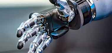
Robot Actuator
Actuator shaft supply for harmonic drive, planetary QDD, and direct-drive actuator module manufacturers — hollow and solid shaft programs covering all torque classes with encoder seat TIR records, hollow bore coaxiality documentation, and bearing interference fit air gauge verification per lot.
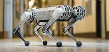
Legged Robot
High-torque 42CrMo4 hollow shafts for quadruped and biped legged robot hip, knee, and ankle actuators — fatigue-rated geometry, impact-tolerant material selection, and robot output shaft in China production economics enabling legged robot hardware at competitive BOM cost.
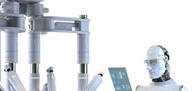
Surgical Robot
316L stainless and Ti-6Al-4V robot output shafts for surgical robotic wrist and instrument drive joint actuators — non-magnetic materials, Ra 0.1μm journals, ASTM A967 passivation, and documentation compatible with medical-device configuration control.
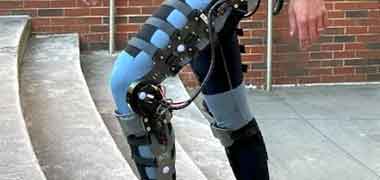
Exoskeleton & Industrial Robot
Lightweight hollow robot output shafts for exoskeleton joint actuators without tooling investment for clinical evaluation runs, alongside high-volume actuator shaft programs for industrial robot joint modules at 10,000–500,000 annual units with dedicated MAZAK capacity for production line continuity.
Robot Output Shaft Machining
Process & Capabilities
CNCPioneer's robot output shaft machining process takes actuator shaft and hollow shaft requirements from initial specification through volume-qualified production in four structured phases — 24-hour DFM review, prototype machining (5–14 days), dimensional verification, and production qualification — with minimum development iteration and maximum schedule predictability.
Robot Output Shaft DFM Review (24 Hours)
Single-setup concentricity feasibility for the customer's torque class and journal spacing · Hollow shaft wall thickness adequacy against torsional stiffness requirement · Encoder seat concentricity budget analysis · Bearing interference class specification for the customer's bearing model · Output flange face perpendicularity achievability review.
Prototype Robot Output Shaft Machining (5–14 Days)
78+ Swiss CNC lathes (miniature finger and wrist shafts Ø8–18mm) and 66+ MAZAK mill-turn centers (complex hollow shaft bodies and integrated flange geometry Ø18–120mm) · 17-4PH H900 solid shafts 5–7 days; 42CrMo4 through-hardened 8–12 days; hollow shaft with gun drilling 7–10 days.
Dimensional Verification & First Article
Complete CMM dimensional report on all journal diameters, face perpendicularity, and bolt circles · Roundness tester verification of journal roundness, journal-to-journal concentricity ±0.002mm, and encoder seat TIR ≤0.003mm · Hollow shaft bore coaxiality CMM at 5 axial positions · Mass verification ±0.5g.
Production & Statistical Control
PPAP Level 3 qualification with Cpk ≥1.67 on output journal diameter and encoder seat TIR · 100% laser micrometer on all output journals above 5,000 units annually · Adaptive CNC diameter offset correction for tool-wear drift · Blanket order programs with committed monthly release lead times.
Robot Output Shaft Materials
17-4PH H900 · 42CrMo4 through-hardened and nitrided · 20CrMnTi case-hardened · 316L · Ti-6Al-4V · 7075-T6 · GCr15 bearing steel — all materials sourced with full mill certificates and SII XRF composition verification.
IATF 16949 / AS9100D Quality Documentation
CoC, laser micrometer journal records, roundness tester concentricity and TIR charts, CMM dimensional report, hollow shaft bore coaxiality records, material certifications with lot traceability, aging and heat treatment records, and PPAP Level 3 for volume programs.
Materials for Robot Output Shafts
Robot output shaft material selection is governed by yield strength for torque transmission at minimum cross-section, hardness for bearing journal fatigue life, corrosion resistance in human-facing joint environments, and machinability for journal and hollow-bore precision. 17-4PH H900 is the dominant material for the majority of robot output shaft programs globally.
17-4PH H900
1,310 MPa yield · HRC 44–47 · Corrosion resistant, no post-machine heat treatment distortion — the standard robot output shaft material across roughly half of all humanoid and cobot actuator shaft programs, machinable in the solution-annealed condition before final aging
316L
485 MPa yield · Non-magnetic, biocompatible · Surgical robot wrist and instrument drive output shafts, and MRI-adjacent joint actuator shafts where ferromagnetic materials would corrupt imaging or sensing performance
42CrMo4 (Through-Hardened)
1,000 MPa yield · HRC 28–34 · Maximum toughness for heel-strike and impact loading — specified for knee and hip robot output shafts at 150–350 Nm torque class where 17-4PH's lower impact energy makes brittle fracture more likely
42CrMo4 (Nitrided)
Surface HRC 58–62, 0.1–0.3mm case depth · Bearing-quality journal hardness without full through-hardening distortion — post-nitride cylindrical grinding restores ±0.002mm diameter and Ra 0.1μm on all bearing journals
20CrMnTi
Surface HRC 60–62, tough core · Robot output shafts with integrated gear zones where the shaft body doubles as a gear element, combining a hard wear surface with a ductile core resisting fatigue crack propagation
GCr15
HRC 62–65 · Maximum surface fatigue resistance · Integrated bearing-race robot output shaft designs where the journal itself functions as an inner race surface under sustained rolling contact load
Ti-6Al-4V
950 MPa yield · Lightest structural option, non-magnetic · Weight-critical distal joint shafts (finger, wrist) and MRI-compatible hollow shafts for surgical and MRI-adjacent robot programs
7075-T6
503 MPa yield · 65% lighter than steel · Low-torque QDD output shafts and exoskeleton joint programs prioritizing minimum rotational inertia over maximum torque capacity
Surface Treatments for
Robot Output Shafts
Robot output shaft surface treatment selection is governed by corrosion resistance in human-facing joint environments, dimensional allowance on precision journals, low-friction requirements for hollow shaft cable-to-bore contact, and bearing journal wear resistance under sustained rolling contact load.
Passivation — ASTM A967
Mandatory for all 17-4PH H900 and 316L stainless robot output shaft components — removes machining-process free iron and restores the passive chromium oxide layer for maximum corrosion resistance. Zero dimensional change, applicable directly on ±0.002mm bearing journals without allowance.
Black Oxide
Low-reflectance mild corrosion protection for 42CrMo4 steel robot output shafts in camera-adjacent joint locations — minimal dimensional change (≤0.0002mm), compatible with ±0.002mm journal tolerances without allowance.
Electroless Nickel — MIL-C-26074
Corrosion protection for steel robot output shafts in corrosion-exposed joint environments, and lubrication-enhancing coating for hollow shaft interior bores reducing cable-to-bore friction. Plating allowance (0.010–0.020mm per surface) built into machined journal dimensions.
DLC Coating — 1–3μm
Ultra-low friction (μ 0.05–0.15 dry) for seal running surfaces and hollow shaft bore interiors where cable contact occurs during joint rotation — reduces cable-to-bore friction 60–70% versus uncoated aluminum or steel. Coating thickness incorporated in the bore diameter machined dimension.
Nitriding (Gas or Plasma)
Case-hardened surface HRC 58–62, 0.1–0.3mm case depth for 42CrMo4 shafts requiring bearing-quality journal hardness without full through-hardening distortion. Post-nitride cylindrical grinding restores ±0.002mm diameter and Ra 0.1μm surface finish.
Hard Chrome — 0.005–0.025mm
Wear-resistant coating for lip seal running surfaces and high-wear sliding contact zones on robot output shafts. Post-chrome grinding restores bearing-quality surface finish and diameter precision on chrome-plated journal zones.
All robot output shaft surface treatments — passivation, black oxide, electroless nickel, DLC coating, nitriding, and hard chrome — are applied with dimensional allowance built into the machined feature so post-treatment journals land within specification. Surface treatment certifications are included in the shipment documentation package for every program.
IATF 16949 / AS9100D Quality System
for Robot Output Shafts
A robot output shaft that passes individual feature inspection but fails assembled concentricity produces bearing friction, encoder noise, and joint misalignment that control engineers often attribute to design problems rather than manufacturing process failure. CNCPioneer's quality system is built to catch exactly this failure mode.
Contract & Drawing Review
Engineering and quality review of robot output shaft drawing requirements, concentricity callouts, hollow shaft bore specifications, and bearing interference class before order acceptance. All drawing ambiguities resolved with the customer before production release.
Material Incoming Inspection
SII XRF composition verification confirms base alloy compliance for 17-4PH (Cu 3.0–5.0%, Ni 3.0–5.0%, Cr 15.0–17.5%), 42CrMo4 (Mo 0.15–0.30%, Cr 0.90–1.20%), and Ti-6Al-4V (Al 5.5–6.5%, V 3.5–4.5%) stock; hardness verification post-aging or post-heat-treatment; full mill-certificate-to-serial-number lot traceability.
First-Off & In-Process Verification
First-off laser micrometer on all output journals before batch release. Hollow shaft bore position CMM at 3 axial positions after gun drilling, before boring bar finish — confirming straightness within ±0.030mm before committing to bore finish investment.
In-Process Statistical Control
In-process journal diameter gauging with adaptive offset correction detecting tool-wear drift and correcting within ±0.001mm before approaching control limits. SPC control charts on output journal diameter, encoder seat TIR, and hollow shaft bore coaxiality.
Final Inspection
Laser micrometer on all bearing journals ±0.002mm (100% on precision programs). Roundness tester: journal roundness ±0.001mm, encoder seat TIR ≤0.003mm, journal-to-journal concentricity ±0.002mm. CMM (±0.001mm): flange perpendicularity, bolt circle, hollow shaft bore coaxiality at 5 positions.
Shipment Documentation
CoC, laser micrometer journal records, roundness tester concentricity and TIR charts, CMM dimensional report, hollow shaft bore coaxiality records, material certifications with lot traceability, and PPAP Level 3 for volume programs.
IATF 16949 / AS9100D Quality System
Details
CNCPioneer's IATF 16949 and AS9100D certified robot output shaft machining factory confirms independent audit compliance with the quality management framework demanded by humanoid robot OEMs and industrial robot prime contractors alike.
Dimensional Documentation Package
Complete CMM dimensional report, roundness tester concentricity and encoder seat TIR charts, and hollow shaft bore coaxiality measurement at 5 axial positions for every production lot. Records retained for program configuration management.
- CMM report every lot
- Encoder seat TIR charted
- Records retained long-term
Material Traceability & Authentication
Full material traceability chain from mill certificate heat number through finished robot output shaft shipment. SII XRF composition verification on incoming material for every order. Counterfeit material prevention through approved supplier list management.
- XRF alloy verification every order
- Mill cert heat number traced
- Counterfeit part prevention
Cpk ≥ 1.67 Process Capability
PPAP Level 3 qualification with Cpk ≥1.67 on output journal diameter and encoder seat TIR special characteristics; Cpk ≥1.33 on journal-to-journal concentricity. MSA Gage R&R on all gauging systems for volume programs.
- Cpk ≥ 1.67 on key characteristics
- PPAP Level 3 for volume programs
- Certificate of Conformance (C of C)
Robot Output Shafts FAQ
Common questions from humanoid robot OEMs, actuator module producers, and industrial robot manufacturers about CNCPioneer's robot output shaft machining capability, single-setup concentricity, and hollow shaft engineering.
A robot output shaft is the precision-machined component that transmits an actuator's reduced torque from the gearbox to the robot's structural link, while providing the bearing journal seats, encoder coupling interface, output flange face, and — in hollow designs — the through-bore for cable routing. It occupies a uniquely consequential position because every actuator subsystem intersects on it: a 0.005mm journal concentricity error misaligns bearings and increases friction 40–80% above design value; a 0.010mm flange perpendicularity error tilts the structural link off the kinematic axis in a way calibration cannot fully correct; and a 0.005mm encoder seat runout introduces a once-per-revolution position error the force controller fights with unnecessary control effort. Getting the shaft right is what makes every other actuator component perform to its own specification.
Hollow shafts are near-universal in modern humanoid joint design because routing motor power, encoder, and communication cables through the joint's rotation axis is the only practical way to maintain cable integrity across millions of rotation cycles without external loops that bind or wear. Solid shafts remain the right choice where the structural link routes cables externally, or where battery/wireless architectures eliminate through-shaft routing entirely — they're simpler to machine and impose no torsional stiffness penalty. The trade-off is quantifiable: removing a bore reduces torsional stiffness by 1 − (D_bore/D_OD)⁴, which is negligible below a 0.6 bore-to-OD ratio and becomes a real design consideration above it. CNCPioneer's DFM review runs this calculation against the joint's torsional compliance budget before committing to either architecture.
Journal-to-journal concentricity specifications (±0.002mm between front and rear bearing journals) are incompatible with the chuck re-registration error (±0.010–0.030mm) that occurs every time a shaft is re-fixtured between separate operations. A shaft finish-turned on the front journal, then rechucked to machine the rear journal, can have both journals individually within tolerance and roundness spec — yet be completely non-conforming on the ±0.002mm concentricity that governs assembled performance. The result: bearings preloaded into misalignment (40–80% higher friction), gearbox axes offset enough to generate transmission error at the orbital frequency, and — if the encoder seat is referenced to the wrong journal — position error control engineers often trace to "encoder noise" rather than the shaft. CNCPioneer's MAZAK mill-turn single-setup programs machine every journal from one datum without rechucking, so concentricity is governed by machine positioning accuracy (±0.001mm) rather than re-registration uncertainty.
Bore coaxiality should be set by the cable's fatigue tolerance at the bore exit, not a default precision value. If the bore center sits 0.010mm eccentric to the shaft's rotation axis, the bore exit point traces a 0.020mm-diameter circle every rotation, forcing the cable through a cyclic bend of that amplitude. Over roughly 10⁶ rotations, that cycling measurably shortens cable life. For standard programs, ±0.005mm bore coaxiality keeps bore exit excursion under 0.010mm — within tolerance for typical motor leads and encoder cables. High-duty-cycle robots (continuous operation above 2 Hz average joint rotation) or fragile flex-circuit cables warrant tightening to ±0.003mm. CNCPioneer's DFM review runs this calculation against the customer's actual cable type and joint duty cycle rather than defaulting to a number that may be needlessly tight or too loose.
Interference class follows ISO 286 shaft tolerance guidance for bearing inner rings, chosen against whether the inner ring rotates under load, bearing size, and load character. For the common rotating-inner-ring configuration, ISO 286 class k5 (3–18μm interference) suits wrist, elbow, and shoulder shafts under moderate radial load where hand or moderate hydraulic pressing is acceptable; class m5 (6–24μm) suits knee and hip shafts under heavy or impact radial loading, including gait impact, where ring slip under peak load is the concern. Bearing manufacturers typically specify ±0.003mm accuracy within the chosen class; CNCPioneer machines journals to ±0.002mm within class — tighter than that specification — to hold margin against gauge uncertainty, verified by 100% laser micrometer with SPC confirming Cpk ≥1.67 against the interference target band.
Prototype lead times: solid 17-4PH H900 standard configuration 5–7 business days; 42CrMo4 through-hardened (with heat treatment) 8–12 days; hollow shaft with gun drilling 7–10 days; large-diameter hollow shaft in 42CrMo4 10–14 days; complex multi-feature shafts (hollow + splined bore + encoder disc seat + integral flange) 10–14 days. Pilot production (25–500 units) runs 2–4 weeks per batch; PPAP Level 3 qualification takes 6–8 weeks from pilot data completeness. Volume production ships on 2–3 week monthly blanket releases, with annual capacity of 500,000+ units across all joint torque classes on 66+ MAZAK mill-turn platforms. Kit programs coordinating shafts with bearing sleeves, preload spacers, and housing components for synchronized delivery are standard for humanoid OEM programs above 50 robot builds monthly.
Get a Quote for Robot Output Shafts
Upload your robot output shaft or hollow shaft drawings or CAD files and receive a free DFM review and competitive quotation within 24 hours — covering single-setup concentricity feasibility, hollow shaft bore coaxiality and torsional stiffness analysis, encoder seat TIR budget, bearing interference class specification, and complete pricing from prototype through volume production.