
Robot Structural Links
& CNC Brackets
CNCPioneer is a precision robot structural components specialist and certified China robot structural components manufacturer delivering custom arm links, leg links, torso frame brackets, base frame structural bodies, and CNC joint interface brackets with structural interface position accuracy of ±0.010mm, pivot bore center distance of ±0.005mm, topology-optimized wall uniformity of ±0.050mm, and mass verification to ±0.5g — left/right matched pair differential ≤0.5g — operating 66+ MAZAK mill-turn centers, MAZAK VARIAXIS 5-axis platforms, and 78+ Swiss CNC lathes since 2011.

What Are Robot Structural
Links & Brackets?
Robot structural links and brackets are the precision-machined load-bearing elements that constitute the physical skeleton of every robot system — the structural members connecting actuated joints along kinematic chains, the bracket bodies coupling actuator outputs to limb segments, the frame structural components establishing the fixed reference structure from which all kinematic motion derives, and the interface brackets coupling sensors, end-effectors, and accessory hardware to the robot's structural body.
Robot structural components differ from general industrial hardware in three engineering realities: kinematic precision (every dimension enters the robot's kinematic model directly), stiffness-to-mass optimization (topology-optimized geometry at ±0.050mm wall uniformity), and fatigue life (10⁶–10⁸ load cycles requiring load-path fillet radii verified to ±0.05mm). A link length 0.5mm longer than designed, or a bracket interface 0.3mm off-position, produces systematic end-effector position error proportional to the deviation multiplied by the kinematic amplification factor from that structural location to the end-effector.
-
Kinematic precision as a quality discipline Interface position tolerances (±0.010mm standard; ±0.005mm high-precision) specified from kinematic amplification factor analysis — not arbitrary drawing callouts — ensuring robot end-effector accuracy from production parts.
-
Stiffness-to-mass optimization, verified Every lightweight link DFM checks mass, natural frequency (above servo bandwidth), and 10⁷-cycle fatigue life simultaneously — preventing designs that achieve mass targets but fail stiffness or fatigue in robot testing.
-
Complete structural portfolio, one relationship Arm links, leg links, torso brackets, base frames, and end-effector adapters across MAZAK VARIAXIS 5-axis, MAZAK mill-turn, and Swiss CNC — coordinated to one robot build schedule.
-
Bilateral matched pair verification, standard Every left/right structural pair CMM-verified for dimensional differential ≤0.010mm and mass differential ≤0.5g — shipped with as-built records for whole-body controller bilateral inertia initialization.

Why CNCPioneer as Your Robot
Structural Components Manufacturer?
Every dimension in a robot structural link or CNC bracket directly enters the robot's kinematic model. CNCPioneer's structural component programs address kinematic precision, stiffness engineering, and fatigue compliance — not just dimensional tolerances — separating structural hardware that performs in the field from parts that only pass inspection.
Kinematic Precision as a Quality Discipline
Every DFM calculates the kinematic amplification factor from each structural interface's position error to end-effector error — then specifies tolerances (±0.010mm standard; ±0.005mm high-precision) that ensure the assembled kinematic chain achieves the end-effector accuracy specification from production parts, not only prototypes.
Lightweight Links as a Stiffness Engineering Discipline
Every lightweight link DFM verifies mass, first natural frequency (above servo bandwidth), and 10⁷-cycle fatigue life simultaneously — because topology-optimized designs that achieve mass targets but fail stiffness or fatigue requirements are discovered only after robot system testing without this analysis.
CNC Brackets as Precision Kinematic Elements
CNC brackets are not mounting hardware — they are precision kinematic elements whose bore center distances (±0.005mm), bore perpendicularity (±0.02°), and interface positions (±0.010mm) determine whether the assembled robot behaves as its kinematic model predicts. 100% CMM verification on every program.
Load-Path Fillet Radius as a Fatigue Quality Gate
Every load-path fillet verified by optical comparator to ±0.05mm — because an undersized fillet of 0.5mm at a bracket bore shoulder can reduce fatigue life from 2×10⁷ cycles to 8×10⁶ cycles, the difference between a robot that outlasts its product generation and one requiring field replacement within two years.
Complete Structural Portfolio, All Robot Types
Humanoid arm/leg links, cobot serial link bodies, industrial robot axis links, legged robot structural tubes, AMR chassis members, exoskeleton frames, and surgical arm links — all from one IATF 16949/AS9100D qualified relationship, eliminating the multi-supplier qualification that a full robot structural BOM would otherwise require.
40–60% China Manufacturer Cost Advantage
CNCPioneer's structural component programs deliver 40–60% reduction versus US, European, and Japanese structural suppliers at identical kinematic precision, stiffness verification, fatigue fillet compliance, and IATF 16949 documentation — the BOM economics making custom structural programs commercially viable at scale.
Robot Structural Links & Brackets
We Manufacture
CNCPioneer's robot structural components machining covers the complete structural BOM — arm and leg links through base frame brackets and end-effector adapters — coordinated as one kinematic-verified kit rather than isolated component quotes.

Humanoid Robot Arm Structural Links
Upper arm links (150–380g ±0.5g, actuator interfaces ±0.005mm both ends), forearm links (100–250g, dual actuator mounting ±0.010mm), and modular 6-DOF serial link series with common bolt circle ±0.010mm and register ±0.005mm for assembly flexibility.

Humanoid Robot Leg Structural Links
Thigh links (200–480g ±0.5g, end face perpendicularity ±0.02°), shin links (impact-rated 160–380g, impact FEA verified under 1.8× body weight), and four-bar knee/hip linkage sets (crank/coupler/rocker center distance ±0.005mm) — all bilateral matched pairs ≤0.5g differential.

Industrial Robot Arm Serial Links
Axis 1–6 structural link bodies for 6-DOF industrial arms — base links in 42CrMo4 or 7075-T6 (wall 5–8mm), upper arm links (3–6mm wall), and wrist link pairs (2.5–4mm wall) with interface position ±0.020mm at Axis 1–3 and ±0.010mm at Axis 4–6.

Collaborative Robot Structural Links
Cobot serial link bodies in 7075-T6 or 6061-T6 (wall 1.5–3mm, cosmetic Ra 0.8μm exterior), internal cable loom channels, IP54 O-ring seal grooves ±0.020mm, and EOAT adapter plates with ISO 9409-1 pilot bore ±0.002mm — IATF 16949 volume production to 500,000+ units annually.

Mobile Robot & AMR Structural Components
AMR chassis cross-member frame links (6061-T6 / 5052-H32, end faces ±0.05°), drive module mounting plates (±0.020mm), gusset corner brackets, battery bay structural rails, and wheeled suspension four-bar links (upper/lower control arms, knuckle brackets with multi-bore position network ±0.020mm).

CNC Brackets — Complete Portfolio
Single-axis pivot brackets (pivot bore ±0.005mm), dual-axis compound brackets (5-axis ±0.02° inter-axis angle), yoke brackets (fork bore coaxiality 0.005mm, root fillet ±0.05mm), cantilever sensor brackets, end-effector adapter plates, F/T sensor interfaces (perpendicularity 0.005mm), and quick-change tool coupler brackets.
Industries & Applications
CNCPioneer's robot structural components supply humanoid robot OEMs, collaborative robot manufacturers, industrial robot builders, legged robot developers, mobile robot producers, exoskeleton companies, surgical robot manufacturers, and service robot developers worldwide.

Humanoid Robot OEMs
Complete custom structural component supply — all arm links, leg links, torso frame brackets, and joint interface CNC brackets — as a single China robot structural components relationship with kinematic DFM, fatigue fillet verification, bilateral matched pairs, and PPAP-qualified volume production.

Collaborative Robot Manufacturers
IATF 16949 certified cobot arm structural link production — lightweight 7075-T6 or 6061-T6 serial link bodies, end-effector adapter brackets, and tool interface CNC brackets at 10,000–500,000 units annually with PPAP Level 3 and cosmetic Ra 0.8μm surface quality.

Industrial Robot Manufacturers
Robot arm serial link production for 6-DOF industrial arm configurations — axis 1 through 6 link bodies, base frame structural brackets, and wrist link CNC brackets at high-volume IATF 16949 production with blanket order scheduling for robot assembly line supply.
Legged Robot Developers
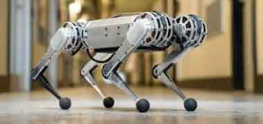
Hip, thigh, shin, and ankle structural link programs for quadruped and biped legged robots — impact-rated structural geometry, fatigue-verified fillet profiles, and bilateral symmetry matching for the high-cycle locomotion loading of legged robot programs.
Mobile Robot & AMR Producers
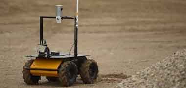
Chassis frame structural links and brackets, suspension link sets, drive module mounting brackets, and end-effector structural adapter plates for AMR programs — 6061-T6 and 5052-H32 structural materials for outdoor and wash-down AMR environments.
Exoskeleton & Surgical Robot Developers
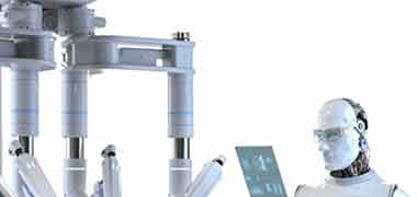
Body-conforming 5-axis profiled structural links for exoskeleton frames and pilot device programs without tooling investment; 316L stainless and Ti-6Al-4V structural brackets and arm links for surgical robotic arm structures — non-magnetic, Ra 0.8μm surfaces, passivation ASTM A967, ISO 13485-compatible documentation.
Robot Structural Links & Brackets
Process & Capabilities
CNCPioneer's structural components process takes robot structural designs from CAD or BOM through PPAP-qualified volume production — 24-hour structural DFM review, prototype kit delivery (5–28 days), and full kinematic-fatigue qualification.
Structural DFM Review (24 Hours)
Kinematic amplification factor calculation per interface · Stiffness natural frequency analysis · Fatigue life at all fillet-critical locations · Mass target pre-check · Topology optimization pocket feasibility · Left/right symmetry specification · Compound-angle 5-axis routing determination.
Prototype Structural Kit (5–28 Days)
Simple 7075-T6 link or bracket 5–7 days; 5-axis topology-optimized link 8–12 days; dual-axis compound bracket 8–12 days; yoke bracket (5-axis) 9–14 days; Ti-6Al-4V structural link 10–14 days; bilateral matched pair +2 days; complete single-robot structural kit 18–28 days.
Bilateral Pair Verification
Every left/right structural pair CMM-verified for dimensional differential ≤0.010mm at all structural interfaces, mass differential ≤0.5g, and wall thickness map matched. Records shipped with every bilateral pair for whole-body controller bilateral inertia parameter initialization.
Volume Production & Statistical Control
PPAP Level 3 with Cpk ≥1.67 on structural interface positions, pivot bore center distances, and load-path fillet radii (IATF special characteristics) · Volume pricing 62–72% below prototype at 1,000+ units · 2–3 week monthly blanket releases · 2,000,000+ unit annual capacity.
Structural Component Materials
7075-T6 (65% of programs) · 6061-T6 · 6063-T5 · 5052-H32 · AZ91D · Ti-6Al-4V · 17-4PH H900 · 316L · 42CrMo4 · PEEK — all sourced with full mill certificates and SII XRF composition verification per lot.
IATF 16949 / AS9100D Documentation
CoC, CMM reports, optical comparator fillet radius records, ultrasonic wall maps, mass balance records with bilateral differential, profilometer surface finish records, material certifications, PPAP Level 3, FAIR per AS9102 for defense and aerospace programs.
Materials for Robot Structural
Links & Brackets
Structural component material selection is governed by specific fatigue (fatigue endurance per unit density), required stiffness, and mass budget. 7075-T6 covers roughly 65% of programs; Ti-6Al-4V's specific fatigue of 113 MPa·cm³/g — 2× higher than 7075-T6 — makes it the correct choice for highest-load humanoid hip fork and knee bracket structural links despite its higher density.
7075-T6
2.80 g/cm³ · 160 MPa fatigue endurance · Specific fatigue 57 MPa·cm³/g · Standard arm/leg links and CNC brackets — roughly 65% of all robot structural component programs
6061-T6
2.70 g/cm³ · 96 MPa fatigue endurance · Excellent machinability, cosmetic anodize · Low-stress structural brackets, covers, cobot serial links, and EOAT adapter plates
5052-H32
2.68 g/cm³ · 115 MPa fatigue endurance · Superior corrosion resistance · Outdoor and wash-down AMR chassis structural frame links and mobile robot bracket programs
Ti-6Al-4V
4.43 g/cm³ · 500 MPa fatigue endurance · Specific fatigue 113 MPa·cm³/g — 2× 7075-T6 · High-load humanoid hip fork, knee yoke brackets, and shoulder links where fatigue life demands walls thinner than aluminum can provide
AZ91D
1.81 g/cm³ · 70 MPa fatigue endurance · Lowest density structural alloy · Mass-critical distal arm and leg links where minimum link inertia is the primary design constraint (NFPA 484 fire safety protocol applied)
17-4PH H900
7.75 g/cm³ · 620 MPa fatigue endurance · Specific fatigue 80 MPa·cm³/g · High-stress brackets, flanges, pivot yokes, and end-effector adapters where stiffness and corrosion resistance both matter
316L
7.99 g/cm³ · 200 MPa fatigue endurance · Non-magnetic, sterilization-compatible · Surgical robot structural brackets and corrosion-exposed structural members requiring ISO 13485-compatible documentation
42CrMo4
7.85 g/cm³ · 450 MPa fatigue endurance · Specific fatigue 57 MPa·cm³/g · Heavy-duty industrial robot base frames, robot track links, and axis 1–2 structural bodies where maximum stiffness governs over mass
PEEK
1.32 g/cm³ · 50 MPa fatigue endurance · Electrically insulating, self-lubricating · Isolation brackets and low-load dielectric structural elements requiring EMC bonding separation in robot structural assemblies
Surface Treatments for
Robot Structural Links & Brackets
Structural component surface treatment selection is governed by pivot bore wear resistance, fatigue zone protection, corrosion protection for magnesium links, and EMC bonding continuity — with load-path fillets verified before treatment since anodize does not penetrate small-radius re-entrant geometry.
Black Hard Anodize — MIL-A-8625 Type III
Standard for aluminum robot structural links and CNC brackets — HV 400+ wear resistance at pivot bore surfaces; black color for visual continuity with robot aesthetics. Load-path fillets verified before anodize application since anodize does not penetrate small-radius re-entrant geometry.
Electroless Nickel — MIL-C-26074
Mandatory for AZ91D magnesium structural links — uniform corrosion protection across complex topology-optimized lightweight link geometry including all internal pocket surfaces. Required process step for every AZ91D structural program; coordinated with machining delivery.
Passivation — ASTM A967
Mandatory for all 17-4PH H900 and 316L stainless robot structural brackets and yoke structural links. Zero dimensional change — applied without bore-size allowance on tight-tolerance structural interfaces and pivot bore surfaces.
Type II Clear Anodize
Cosmetic and corrosion protection for collaborative robot structural links where black Type III conflicts with robot color design. ASTM E595 TML ≤0.05% for cleanroom structural bracket programs requiring outgassing compliance.
DLC Coating — 1–3μm
Ultra-low friction for pivot bore surfaces in high-cycle structural bracket pivots using plain bearings — reducing friction coefficient from μ≈0.15 (anodized aluminum) to μ≈0.06 (DLC), extending pivot bearing life at gait-cycle rates across 10⁷+ locomotion cycles.
Shot Peening
Compressive surface stress induction at fatigue-critical fillet zones in high-cycle structural links — increasing effective fatigue endurance 15–30% at shot-peened surfaces. Standard optional process for hip fork, knee bracket, and shin tube programs where fatigue margin from geometry and material alone is below 1.5× safety factor.
All robot structural links and brackets surface treatments — hard anodize, electroless nickel, passivation, clear anodize, DLC, and shot peening — are specified with dimensional allowance built into the machined bore or structural interface before treatment. Treatment certifications are included in the shipment documentation package for every program.
IATF 16949 / AS9100D Quality System
for Robot Structural Links & Brackets
Structural interface position, load-path fillet radius, wall thickness, and bilateral mass matching are four quality dimensions that determine whether robot structural components perform as their kinematic and fatigue models predict. CNCPioneer verifies all four — not just individual dimensions.
Kinematic-Structural DFM Review
Kinematic amplification factor per interface, stiffness natural frequency analysis, fatigue life at all fillet-critical locations, mass target check, topology optimization feasibility, bilateral symmetry spec, and 5-axis routing determination — completed in 24 hours before machining commitment.
Load-Path Fillet Radius Verification
Every load-path fillet on every structural link and CNC bracket verified by optical comparator or CMM scan to ±0.05mm before surface treatment. Out-of-specification fillets rejected at this gate — fillet records archived per component lot for fatigue traceability.
Structural Interface Position — 100% CMM
100% CMM on pivot bore center distances, structural interface positions, and compound-angle bracket inter-bore angular relationships. SPC control charts on interface positions with Cpk ≥1.67 on IATF 16949 special characteristics.
Material Incoming Inspection
SII XRF composition verification — 7075-T6, 6061-T6, AZ91D, Ti-6Al-4V, 17-4PH H900, 42CrMo4. Hardness verification post-aging on 17-4PH (44–47 HRC). Full material certificate-to-robot-serial-number lot traceability.
Mass & Bilateral Symmetry Verification
Every robot structural link and CNC bracket weighed to ±0.5g against design target. Left/right pairs verified as matched sets — mass differential records and CMM dimension differential records shipped with every bilateral pair lot for controller parameter initialization.
Documentation
CoC, CMM dimensional reports, fillet radius verification records, mass records with bilateral pair differential, ultrasonic wall maps, profilometer surface finish records, material certifications, anodize/electroless nickel records, shot peening records, PPAP Level 3, FAIR per AS9102.
IATF 16949 / AS9100D Quality System
Details
CNCPioneer's IATF 16949 and AS9100D certified robot structural components facility confirms independent audit compliance with the quality framework demanded by humanoid robot OEMs, collaborative robot manufacturers, and legged robot developers at every volume level.
Structural Interface Position Verification
100% CMM verification of pivot bore center distances, structural interface positions, and compound-angle bracket inter-bore angular relationships on all precision robot structural component programs — with SPC control charts on IATF 16949 special characteristics.
- Interface position ±0.010mm CMM
- Pivot bore center distance ±0.005mm
- Compound angle ±0.02° verified
Load-Path Fillet Radius — Fatigue Gate
Every load-path fillet on every structural link and CNC bracket verified by optical comparator or CMM scan to ±0.05mm before surface treatment. Out-of-specification fillets rejected before treatment — fillet records archived per component lot for fatigue traceability throughout the robot's service life.
- 100% optical comparator on fatigue fillets
- ±0.05mm fillet radius tolerance
- Records archived per component lot
Material Traceability & Cpk ≥ 1.67
Full material traceability from mill certificate through finished component shipment. PPAP Level 3 qualification with Cpk ≥1.67 on structural interface positions, pivot bore center distances, and load-path fillet radii — the IATF 16949 special characteristics for volume robot structural programs.
- XRF alloy verification per lot
- Cpk ≥ 1.67 on all special characteristics
- PPAP Level 3 for volume programs
Bearing Sleeve Free-State Bore Quality Protocol
CNCPioneer's bearing sleeve low-force clamping protocol verifies that bore roundness (±0.001mm) and concentricity (±0.003mm) measurements reflect free-state sleeve geometry — not chuck-distorted geometry that springs back to non-round dimensions after unclamping.
- Low-force protocol on wall/D ratio <0.15
- Bore roundness ±0.001mm free-state verified
- Concentricity ±0.003mm at reduced clamp force
Robot Structural Links & Brackets FAQ
Common questions from humanoid robot OEMs, collaborative robot manufacturers, industrial robot builders, and legged robot developers about CNCPioneer's robot structural component engineering, kinematic precision, and bilateral matching programs.
The correct structural interface tolerance derives from the kinematic amplification factor from that interface's location to the robot's end-effector. For a 6-DOF serial arm: the kinematic amplification factor ranges from approximately 1× at the last joint (near end-effector) to 5–10× at the base joint (far from end-effector, long moment arms). A ±0.010mm position error at the base link bracket produces ±0.05–0.10mm end-effector error, while the same error at the last wrist bracket produces only ±0.010mm end-effector error. The correct tolerance allocation: tighter tolerances (±0.005mm) at high-amplification base links; standard tolerances (±0.010mm) at mid-chain links; relaxed tolerances (±0.020mm) at low-amplification distal brackets. This allocation achieves the end-effector accuracy specification while saving 15–25% machining cost versus applying uniform ±0.010mm everywhere — CNCPioneer provides this tolerance allocation as standard DFM output for every custom structural component inquiry.
Three disciplines separate CNCPioneer's lightweight links from mass-reduction machining: first, 5-axis true-surface machining following the topology optimizer's organic surface within ±0.050mm rather than 3-axis stepover approximation that adds unnecessary mass (positive scallops) and stress concentrators (negative scallop valleys); second, load-path fillet verification to ±0.05mm at every topology-optimizer-identified stress concentration location rather than treating fillets as cosmetic; and third, ultrasonic wall mapping at 5mm grid spacing confirming that machined wall thicknesses match the topology optimizer's wall thickness field at every location — not just the thinnest visible zone. Legitimate lightweight link design requires simultaneous satisfaction of mass, stiffness (first natural frequency above servo bandwidth), and fatigue constraints. CNCPioneer's DFM verifies all three before machining — preventing the common failure where designs achieving mass targets fail stiffness or fatigue requirements discovered only after first robot assembly.
Bilateral symmetry affects performance through three independent pathways. First, gait symmetry from mass asymmetry: an 8g heavier left thigh structural link creates approximately 3% higher swing-phase inertia for the left leg at identical hip actuator torque, producing step-length asymmetry the whole-body controller must actively correct — reducing walking efficiency and stability margin. CNCPioneer's bilateral mass matching to ±0.5g limits inertia asymmetry to below 0.2%. Second, kinematic asymmetry from link length deviation: a left shin 0.020mm longer than right places the foot 0.020mm further forward per step, creating path deviation of approximately 20mm per 1,000 steps. CNCPioneer's bilateral CMM dimensional differential verification to ±0.010mm limits foot placement deviation to under 10mm per 1,000 steps. Third, bilateral arm manipulation: mass asymmetry between left and right arm structural links produces asymmetric torque output visible as vibration in held objects during symmetric manipulation tasks. CNCPioneer ships all bilateral pairs with dimensional differential and mass differential records for whole-body controller bilateral inertia parameter initialization from first robot power-on.
Individual prototype lead times: aluminum 7075-T6 simple link or bracket 5–7 days; topology-optimized 5-axis structural link 8–12 days; compound-angle dual-axis bracket 8–12 days; yoke bracket (5-axis) 9–14 days; AZ91D magnesium lightweight link with electroless nickel 9–13 days; Ti-6Al-4V structural link 10–14 days; bilateral matched pair adds 2 days for CMM and mass verification. Complete single-robot structural kit: 18–28 days coordinated delivery. Pilot production (25–200 robot structural sets): 3–5 weeks per batch. PPAP Level 3: 6–8 weeks from pilot data completeness. Volume: 2–3 week monthly blanket releases; 2,000,000+ unit annual capacity. A standard 7075-T6 arm serial link costing $95 at US prototype pricing costs approximately $55 at CNCPioneer prototype and $18–22 at 10,000 annual unit volume — for a collaborative robot program at 20,000 annual robots with 8 structural links per robot, China structural component savings of $30–40 per link produce $240,000–$320,000 annual BOM savings.
Get a Quote for Robot Structural Links & Brackets
Upload your robot structural link, CNC bracket, or structural component drawings, assembly models, or robot BOM and receive a free kinematic-structural DFM review and competitive quotation within 24 hours — covering structural interface position tolerance allocation, stiffness natural frequency verification, fatigue life calculation at all fillet-critical locations, mass target pre-check, topology optimization feasibility, bilateral symmetry specification, compound-angle routing assessment, material and surface treatment selection, and complete pricing from prototype through volume production.