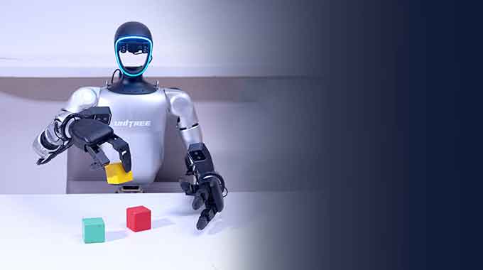
Walk into any robotics lab today and you’ll see the same paradox: humanoid robots that can run, jump, and backflip, but struggle to pick up a pen.
The legs are largely a solved problem. Boston Dynamics spent two decades cracking bipedal locomotion. Unitree brought that capability to the open market for under $20,000. Quadruped and biped motion is now a commodity you can buy off the shelf.
The hands are not. And that gap, between a robot that can walk into a room and a robot that can actually do something useful once it gets there, is the defining engineering challenge of this decade.
Consider what a human hand does in a single morning: button a shirt, crack an egg, type on a keyboard, open a car door, grip a coffee cup without crushing it. Each action requires a different contact geometry, a different force profile, a different coordination between dozens of tendons and 27 bones. The hand contains more nerve endings per square centimeter than almost any other part of the body. It is, by any measure, the most mechanically complex end-effector evolution ever produced.
Replicating it in metal and motors is genuinely hard — not “engineering challenge” hard, but “this is an unsolved research problem” hard. The best dexterous robotic hands in the world cost $50,000 to $150,000 and still can’t match the manipulation capability of a ten-year-old child.
But here’s what’s changed in the last three years: the gap is closing fast. Unitree’s Dex3-1 ships for under $3,000. Inspire Robots sells a 12-DOF hand that researchers actually use. Tesla’s Optimus hand is already threading needles in factory demos. The hardware is becoming accessible. The engineering knowledge is becoming documented.
This guide is the documentation that didn’t exist when you needed it. It covers everything from first principles — why hands are hard, how different actuation approaches trade off against each other — through the design decisions that determine whether your hand will be a demonstration piece or a working tool. The second article in this series covers the CNC manufacturing workflow in detail. This one covers everything you need to know before you make the first cut.
Why Robot Hands Are Uniquely Difficult
Understanding what makes hands hard — specifically — prevents you from solving the wrong problems.
1.1 — The Fundamental Tension: Dexterity vs. Packaging
Every joint you add to a robotic hand must be driven by something. In a human hand, those drivers are muscles located in the forearm, connected to finger bones by long tendons routed through the wrist. The forearm is essentially a remote actuator bank — a brilliant evolutionary solution to a packaging problem.
In a robot hand, you face the same constraint: the fingers themselves have almost no room for motors. A typical human finger is 15–20mm wide. A servo motor that can deliver 1 kg·cm of torque is roughly 12mm in its smallest dimension — and that’s before you add the gearbox, encoder, and mounting hardware.
This single constraint explains almost every design decision in every robotic hand ever built:
- Where do the actuators live? Finger, palm, forearm, or remote?
- How is power transmitted? Direct shaft, tendons, gear trains, hydraulics, pneumatics?
- What do you sacrifice? Force, speed, position accuracy, backdrivability, or simplicity?
There is no design that wins on all axes. Every hand is a different bet on which capabilities matter most.
1.2 — Degrees of Freedom vs. Controllability
A human hand has 21–27 DOF depending on how you count. But the human nervous system doesn’t control each one independently — it uses learned synergies: coordinated joint movement patterns that correspond to common grasp types. Research shows that roughly 80% of everyday manipulation tasks can be accomplished with just 5–7 synergistic movement patterns.
This insight drives the entire field of underactuated hand design:
| DOF Philosophy | Approach | Tradeoff |
|---|---|---|
| Fully actuated | One motor per joint | Maximum control; massive complexity |
| Underactuated | Fewer motors than DOF; joints coupled mechanically | Passive adaptation to object shape; less precise |
| Synergy-driven | Motors drive principal components, not joints | Efficient for common tasks; poor at unusual grasps |
| Fixed-configuration | Rigid fingers, no in-hand manipulation | Simple and strong; no dexterity |
Most practical robot hands today use underactuated or synergy-driven approaches — not because full actuation is impossible, but because the control complexity of 21 independently actuated joints exceeds what real-time systems can reliably manage.
1.3 — The Sensing Problem
A human hand doesn’t just move — it feels. Proprioception tells you where your fingers are. Cutaneous mechanoreceptors tell you what you’re touching, how hard, and whether it’s slipping. Thermoreceptors tell you if it’s hot. Pain receptors stop you before you damage tissue.
Without equivalent sensing, a robot hand operates blind. It cannot:
- Know when an object is about to slip from its grasp
- Adjust grip force for fragile objects without crushing them
- Feel whether a screw is tightening or stripping
- Detect contact geometry to guide in-hand manipulation
Most current robot hands have poor or no tactile sensing. This is not a hardware gap — touch sensors exist. It’s an integration gap: getting 50+ sensor channels from a hand through a wrist without consuming the cable routing space needed for actuator tendons is a genuinely hard packaging problem.
Degrees of Freedom: Designing the Architecture
2.1 — Finger DOF Breakdown
Before choosing an actuation approach, define exactly what your hand needs to do. DOF is the architectural skeleton — change it later and you’re redesigning everything.
Thumb:          4 DOF  →  CMC flexion / CMC abduction / MCP flexion / IP flexion
                          (the thumb makes or breaks grasp versatility)

Index finger:   4 DOF  →  MCP flexion / MCP abduction / PIP flexion / DIP flexion

Middle finger:  3 DOF  →  MCP flexion / PIP flexion / DIP flexion
                          (often DIP coupled to PIP with fixed ratio)

Ring finger:    3 DOF  →  same as middle

Little finger:  3 DOF  →  same as middle + optional MCP abduction

Wrist:          2 DOF  →  flexion-extension / radial-ulnar deviation
              + 1 DOF  →  optional pronation-supination (if not in forearm)

──────────────────────────────────────────────────────────
Full human-equivalent:  ~21 DOF hand + 2 DOF wrist = 23 DOF total
Practical research hand: 12–16 DOF
Practical industrial hand: 6–12 DOF
Minimum viable grasping: 4–6 DOF
──────────────────────────────────────────────────────────
2.2 — DOF Tiers: What You Get at Each Level
| DOF Count | What You Can Do | What You Can’t Do | Examples |
|---|---|---|---|
| 4–6 DOF | Power grasp, pinch grasp, cylindrical grasp | In-hand manipulation, key pinch, tool use | Robotiq 2F-85 gripper |
| 8–12 DOF | Most everyday grasps, basic tool use | Complex in-hand reorientation | Unitree Dex3-1, Inspire RH56 |
| 13–16 DOF | Full grasp taxonomy, simple in-hand manipulation | Fine fingertip tasks | Shadow Hand C6, Wonik Allegro |
| 17–21 DOF | Near-human manipulation capability | Nothing — but control complexity is massive | DLR Hand II, Barrett Hand research |
Practical recommendation for a first build: Target 12–15 DOF. This covers the vast majority of manipulation tasks that make humanoid robots useful, while keeping control complexity manageable and mechanical packaging achievable.
Actuation Methods: The Core Design Decision
This is the decision that determines the character of your entire hand. There is no universally correct answer — each approach has specific strengths that make it the right choice for specific use cases.
3.1 — Method A: Tendon-Driven (Cable-Actuated)
Motors are located remotely — in the palm, forearm, or even the robot’s torso. Cables (tendons) transmit force to the finger joints through pulleys and conduits.
How it works:
Remote Motor + Gearbox
    ↓
Steel cable or Dyneema braid tendon
    ↓
Routed through PTFE-lined conduit channels
    ↓
Finger pulley → joint rotation
Detailed characteristics:
| Attribute | Rating | Notes |
|---|---|---|
| Finger packaging | ★★★★★ | No motors in fingers — slim, lightweight digits |
| Force transmission efficiency | ★★★☆☆ | Friction losses in conduits: 15–35% depending on path |
| Backdrivability | ★★★★☆ | Cables stretch; joints can be pushed back |
| Durability | ★★★☆☆ | Cables fray, conduits wear; maintenance item |
| Complexity | ★★☆☆☆ | Routing, tensioning, and friction compensation are hard |
| Stiffness | ★★★☆☆ | Tendon compliance limits position accuracy |
CNC machining implications:
- Pulley grooves: radius must match cable diameter precisely (±0.05mm) — wrong radius causes cable wear and jump-off
- Conduit entry/exit angles: sharp bends dramatically increase friction — design ≥ 15° minimum bend radius
- Capstan drums: groove pitch must be exact for consistent winding; surface finish Ra ≤ 0.4 µm
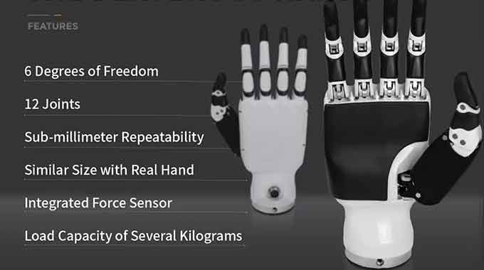
Best for: Human-form hands where visual appearance and finger slenderness matter. Shadow Hand, Unitree Dex3-1, and most research hands use this approach.
3.2 — Method B: Direct-Drive (Motor-in-Finger)
A motor — typically a micro brushless or coreless DC motor — is embedded directly in each finger segment, connected to the joint through a small gearbox or linkage.
How it works:
Micro motor (ø8–16mm BLDC or coreless DC)
    ↓
Micro planetary gearbox (ratio: 50:1 – 150:1)
    ↓
Direct output to joint rotation
Detailed characteristics:
| Attribute | Rating | Notes |
|---|---|---|
| Control simplicity | ★★★★★ | No tendon routing; each joint fully independent |
| Position accuracy | ★★★★★ | No cable stretch; direct mechanical connection |
| Packaging | ★★☆☆☆ | Bulky fingers; hard to achieve human proportions |
| Force output | ★★★☆☆ | Limited by what fits in the finger |
| Backdrivability | ★★☆☆☆ | Gearbox creates reflected inertia |
| Maintenance | ★★★★★ | Simple — motors are accessible and replaceable |
CNC machining implications:
- Motor housings: bore runout ≤ 0.01mm for reliable motor seating
- Gearbox housings: planet carrier bearing fits at H7/p6 — critical for gear mesh quality
- Finger link geometry: complex 3D profiles; 5-axis machining recommended for one-setup accuracy
Best for: Research and prototyping where control simplicity matters more than aesthetics. Wonik Allegro Hand and many academic platforms use this approach.
3.3 — Method C: Pneumatic Actuation
Compressed air drives flexible actuators (pneumatic artificial muscles or bellows) to move finger joints.
Detailed characteristics:
| Attribute | Rating | Notes |
|---|---|---|
| Force density | ★★★★★ | Excellent force-to-weight ratio |
| Compliance | ★★★★★ | Naturally soft; safe for human contact |
| Position control | ★★☆☆☆ | Difficult to achieve precise joint angles |
| Speed | ★★★★☆ | Fast actuation when valves are responsive |
| Infrastructure | ★☆☆☆☆ | Requires compressor, valves, tubing — not portable |
| CNC relevance | Low | Housing and manifolds can be machined |
Best for: Soft robotics research, medical rehabilitation devices, safe human-contact applications. Not suitable for general-purpose humanoid hands.
3.4 — Method D: Shape Memory Alloy (SMA) / Other Exotic
SMA wires contract when heated, acting as linear actuators. Interesting for miniaturization but have severe bandwidth limitations (slow cycle time) and high power consumption. Not recommended for practical hands at this stage.
3.5 — Decision Matrix
| Priority | Best Approach |
|---|---|
| Slender, human-proportioned fingers | Tendon-driven |
| Simple control, easy debugging | Direct-drive |
| Maximum force output | Tendon-driven (remote high-torque motors) |
| Safe human interaction | Pneumatic or tendon with compliant elements |
| CNC machining challenge / precision | Direct-drive (motor housing tolerances are demanding) |
| Production reliability | Direct-drive (fewer wear items) |
Commercial Reference Designs: What the Best Hands Look Like
Before designing from scratch, study what the best current platforms did and why. Every design here is a set of documented engineering tradeoffs.
4.1 — Shadow Dexterous Hand C6
The gold standard for research. The benchmark everything else is measured against.
| Specification | Value |
|---|---|
| DOF | 24 (20 actuated) |
| Actuation | Tendon-driven; 40 pneumatic McKibben muscles |
| Weight | ~4 kg (including forearm actuator pack) |
| Sensing | Position encoders on all joints; optional tactile array |
| Price | ~$150,000 USD |
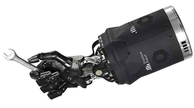
Key design insight: Uses antagonistic muscle pairs — a flexor and extensor tendon for each joint — giving active control in both directions. This is how human fingers work. The result is exceptional compliance and force control, but doubles the actuator count and complexity.
CNC lesson: The Shadow Hand’s finger segments are precision-machined aluminum, not 3D printed. The tendon routing paths are machined channels with smooth, radius-matched transitions. Every mm of routing geometry is deliberate.
4.2 — Unitree Dex3-1
The most important commercial development of the last two years. Accessible pricing changes everything.
| Specification | Value |
|---|---|
| DOF | 7 per hand (thumb: 3 active DOF; each finger: 2 active DOF) |
| Actuation | Tendon-driven; brushless motors in palm |
| Weight | ~580 g |
| Max fingertip force | ~30 N |
| Price | ~$3,000 USD |
Key design insight: Unitree made a deliberate decision to reduce DOF aggressively in exchange for reliability and price. The thumb has 3 DOF (sufficient for most grasps); the fingers are underactuated. The result can handle 70% of real-world manipulation tasks at 3% of Shadow Hand cost.
CNC lesson: The Dex3-1 uses cast and machined aluminum for structural components, with tight tolerances at bearing interfaces and tendon routing exits. The palm housing is a complex multifunction part — cable guide, motor mount, and structural frame in one piece.
4.3 — Wonik Allegro Hand
The most popular direct-drive research platform. Open-source control stack.
| Specification | Value |
|---|---|
| DOF | 16 (4 per finger × 4 fingers) |
| Actuation | Direct-drive; one brushless servo per joint |
| Weight | ~1.1 kg |
| Torque per joint | ~0.7 N·m at finger joints |
| Price | ~$15,000 USD |
Key design insight: Full independent control of every joint makes it the preferred platform for machine learning research — each joint maps cleanly to a control variable. The fingers are bulky by human standards, but the control architecture is the cleanest of any commercial hand.
CNC lesson: The Allegro’s finger segments are machined aluminum with bore features for the servo motors. The tolerances on the motor bores determine whether the joint runs smoothly or binds. This is a precision machining problem masquerading as a robotics problem.
4.4 — Inspire-Robots RH56BFX
China’s most mature commercial dexterous hand. Used in serious research and industrial pilots.
| Specification | Value |
|---|---|
| DOF | 12 (6 per hand; thumb: 2, each finger: 2) |
| Actuation | Tendon-driven; brushless motors in palm housing |
| Weight | ~480 g |
| Fingertip force | ~10 N pinch |
| Price | ~$8,000 USD |
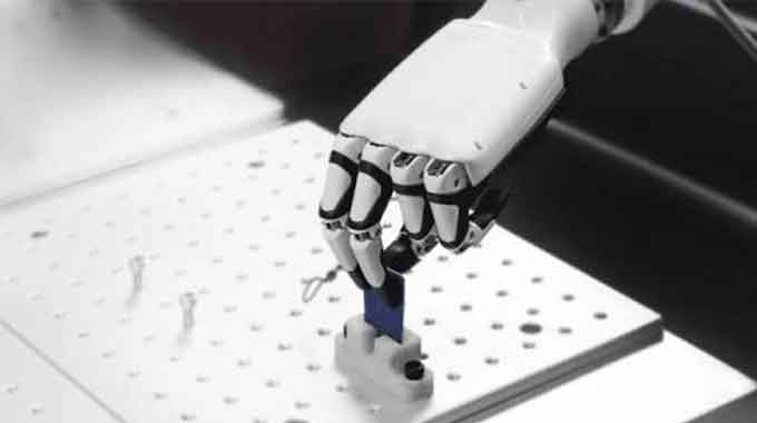
Key design insight: Optimized for industrial grasp reliability over research dexterity. The simplified DOF count means fewer cables to route, fewer failure modes, and faster control loops. It handles the grasps that matter in manufacturing — power grasp, pinch grasp, cylindrical grasp — with high reliability.
Sensor Integration
5.1 — Sensor Types and Their Role
| Sensor Type | Location | Measures | Latency Requirement |
|---|---|---|---|
| Joint position encoder | Each joint | Angular position | < 1 ms |
| Fingertip force/torque | Fingertip pad | Contact force magnitude + direction | < 5 ms |
| Tactile array | Finger pads, palm | Distributed contact pressure map | < 10 ms |
| Tendon tension sensor | Tendon path | Cable tension (for force control) | < 2 ms |
| IMU | Palm | Hand orientation and acceleration | < 5 ms |
| Camera | External or in fingernail | Visual feedback for manipulation | < 30 ms |
5.2 — Joint Position Sensing
For tendon-driven hands, joint-level position sensing is harder than it looks. The motor encoder tells you how much cable you’ve wound — not what angle the joint is at. Compliance and backlash in the tendon path mean these two numbers diverge under load.
Solutions, in order of preference:
Option A: Encoder at the joint (not the motor)
  → Hall effect sensor or optical encoder on joint shaft
  → Best accuracy; hardest to package in small spaces
  → CNC: requires precision bore for sensor and magnet mounting

Option B: Tendon displacement + compliance model
  → Motor encoder + empirical cable stretch correction
  → Requires careful calibration; drifts over time
  → No additional sensors in finger

Option C: Vision-based hand pose estimation
  → External camera + model fitting
  → Works without any joint sensors
  → Latency too high for reactive force control
5.3 — Tactile Sensing — The Hardest Sensing Problem
The fundamental problem with tactile sensing is not the sensors — it’s integration:
- BioTac sensors (SynTouch) work brilliantly but are $2,000 each and fragile
- Barometric sensor arrays (multiple BMP388s in a finger pad) are cheap but low resolution
- Resistive FSR arrays are simple but non-linear and temperature-sensitive
- Capacitive tactile arrays offer the best combination of resolution and robustness
CNC machining challenge: Tactile sensor integration requires precisely machined pockets in fingertip surfaces — too shallow and the sensor protrudes and gets damaged; too deep and contact is lost. Typical tolerance: ±0.05mm on depth, ±0.1mm on position.
5.4 — Recommended Sensor Stack — Practical Build
For a first functional hand, this minimal sensor suite covers the most critical feedback needs:
| Sensor | Quantity | Purpose | Budget |
|---|---|---|---|
| AS5048A magnetic encoder | 1 per motor | Motor position | $3 each |
| FSR 400 force resistor | 5 (one per fingertip) | Contact detection | $5 each |
| BNO085 9-axis IMU | 1 (in palm) | Hand orientation | $15 |
| INA219 current sensor | 1 per motor | Torque estimation via current | $2 each |
Total sensor cost for a 12-DOF hand with 6 motors: roughly $80–120. This gives you contact detection, torque estimation, and orientation — enough to implement basic grasp control.
Control System Architecture
6.1 — The Three Loops
Robotic hand control operates at three timescales simultaneously:
Outer loop  (10–50 Hz)   — Task planning
  "Grasp the cup"
  "Open jar lid"
  "Thread a needle"

Middle loop  (100–500 Hz) — Grasp control
  Pose trajectory generation
  Grasp force regulation
  Slip detection and response

Inner loop   (1–10 kHz)  — Joint servo
  Current control (torque)
  Velocity control
  Position control
The inner loop must run fast enough that the mechanical system never “feels” the discretization. For most robotic hand joints, 1 kHz position control is sufficient; force-sensitive tasks may need 5–10 kHz current control loops.
6.2 — Grasp Planning — The Taxonomy Problem
Not all grasps are equal. Researchers classify human hand grasps into a taxonomy — the Cutkosky Grasp Taxonomy is the most widely used:
Power grasps (whole-hand contact)
├── Cylindrical grasp   →  bottle, pipe, handle
├── Spherical grasp     →  ball, orange, knob
├── Hook grasp          →  carrying a bag
└── Lateral grasp       →  key, card

Precision grasps (fingertip contact)
├── Tip pinch           →  needle, pin
├── Palmar pinch        →  pen, pencil
├── Lateral pinch       →  key turn
└── Tripod grasp        →  cup lid, jar cap
Each grasp maps to a specific joint angle configuration — a “grasp pose.” For a 12-DOF hand, you can predefine 8–12 poses that cover the practical majority of real-world manipulation:
cpp
struct GraspPose {
  float jointAngles[12];
  float graspForce;
  const char* name;
};

GraspPose library[] = {
  { {0, 80, 80, 0, 80, 80, 0, 80, 80, 45, 30, 60}, 5.0, "power_cylindrical" },
  { {0, 40, 50, 0, 40, 50, 0, 40, 50, 60, 40, 70}, 2.0, "precision_pinch" },
  { {0, 90, 90, 0, 90, 90, 0, 90, 90, 90, 60, 80}, 8.0, "power_spherical" },
  // ... more poses
};
6.3 — Force Control — Making the Hand Feel
Position control alone produces stiff, dangerous grasps. Force control — regulating how hard the fingers press, not just where they are — is what makes a hand safe for fragile objects and responsive to slip.
Impedance control is the preferred approach for dexterous manipulation:
cpp
// Impedance control: treat each joint as a spring-damper
// instead of a pure position servo

float torque = Kp * (q_desired - q_actual)    // spring
             + Kd * (dq_desired - dq_actual)  // damper
             + Ki * integral_error;           // steady-state

// When force exceeds threshold, back off
if (fingertipForce > FORCE_LIMIT) {
  q_desired -= COMPLIANCE_FACTOR * (fingertipForce - FORCE_LIMIT);
}
This produces a hand that compresses slightly when it encounters resistance rather than forcing through — critical for handling eggs, electronics, or human hands.
Testing & Validation Protocol
7.1 — Test Sequence
Individual joint range-of-motion check (no load)
→ Joint force output calibration (compare current → torque model)
→ Single-finger grasp attempt (cylindrical object)
→ Full-hand power grasp sequence
→ Precision pinch (small object, <10mm)
→ Sustained force test (hold at target force for 60 seconds)
→ Slip detection and recovery test
→ Fatigue cycle test (1000 open/close cycles)
7.2 — Metrics That Matter
| Metric | Measurement Method | Target |
|---|---|---|
| Joint position accuracy | Command angle vs. measured angle | < 1° RMS |
| Fingertip force accuracy | Commanded vs. load cell | < 5% error |
| Grasp success rate | 20 trials per object type | > 90% |
| Cycle time (open → closed) | Timer trigger | < 500 ms |
| Force repeatability | 20 identical grasp commands | < 3% variation |
| Tendon fatigue life | Cycles to first failure | > 100,000 cycles |
7.3 — The Slip Test — Most Important Single Test
Pick up a smooth cylindrical object — a metal cup, a glass bottle. Command a grasp force near the slip threshold. Then slowly reduce commanded force until the object slips. Note the slip force. Repeat 20 times.
A hand with good force control should show:
- Consistent slip threshold across trials (< 10% variation)
- No sudden drops — smooth, predictable contact loss
- Recovery within 200 ms once slip is detected
A hand with poor force control shows high trial-to-trial variation, sudden drops, and inconsistent behavior. These are symptoms of either poor sensor feedback, tendon compliance without compensation, or inadequate motor bandwidth.
Common Problems and Solutions
| Symptom | Root Cause | Solution |
|---|---|---|
| Finger joints bind mid-range | Tendon routing angle causes side load | Redesign conduit exit geometry; add intermediate routing point |
| Tendons fray quickly | Pulley groove radius mismatch with cable diameter | Machine pulleys to exact cable radius + 0.1mm clearance |
| Fingertip force drifts over time | Tendon creep under sustained load | Use low-creep Dyneema SK75 braid; add tension compensation in firmware |
| In-hand object drops without warning | No slip detection or slow response | Add FSR sensors at fingertips; reduce slip detection latency to < 10ms |
| Motor overheating during sustained grasp | High current for static hold torque | Add torque hold-down: reduce current after grasp is established |
| Position accuracy degrades with temperature | Motor KV changes with winding temperature | Implement temperature-compensated position model |
| Fingers collide with each other | No joint-space collision checking | Add collision avoidance in motion planner; define forbidden joint space regions |
| Poor pinch grasp on small objects | Fingertip geometry wrong for precision contact | Machine dedicated precision-contact fingertip inserts with concave pad surface |
Development Roadmap
Minimum viable grasping hand  (4–6 DOF, underactuated)
  → Proves mechanical concept; tests cable routing and basic control
  → Timeline: 2–3 months

Functional research hand  (12–15 DOF, tendon-driven)
  → Full grasp taxonomy; basic slip detection; force control
  → Timeline: 4–6 months from validated MVP

Integrated system  (hand + wrist + forearm actuator pack)
  → Self-contained unit that mounts to humanoid arm
  → Timeline: 6–9 months

Dexterous manipulation  (in-hand reorientation, tool use)
  → Requires tactile sensing + learning-based control
  → Timeline: 12–18 months; partially open research problem
Summary — Why This Is the Right Problem to Work On
The robot hand problem has two properties that make it ideal for a skilled CNC machinist to tackle:
The mechanical precision gap is real and decisive. Most hobbyist robot hands fail because their parts aren’t accurate enough — tendon routing paths have sharp edges, pulley grooves don’t match cable diameters, bearing fits are sloppy. These are not software problems. They are machining problems. A builder with access to a real CNC machine and the knowledge to use it properly can produce hands that simply work better than anything a 3D printer can build.
The knowledge gap is larger than the hardware gap. Excellent components are increasingly available. What’s missing is clear, depth-first documentation of how to integrate them into a working system. The second article in this series — covering the CNC manufacturing workflow for every major hand component — is exactly that documentation.