Home » Building a Humanoid Robot with CNC Machined Parts
Building a Humanoid Robot with CNC Machined Parts
Written by
Ryan Wang
Last updated on
read
Share:
Table of Contents
We are living through a remarkable moment in robotics history. In just the past few years, humanoid robots have leapt from science fiction into factory floors and research labs. Boston Dynamics’ Atlas backflips. Tesla’s Optimus folds laundry. Unitree’s H1 runs at nearly 4 meters per second. What once required billion-dollar programs is now within reach of small teams and dedicated individuals — and that window of opportunity is wide open right now.
But why humanoid, specifically? The answer lies in the world we’ve already built. Stairs, door handles, tools, vehicles, workspaces — all of it was designed for a body shaped like ours. A humanoid robot doesn’t need the world to be modified for it. It can operate a drill press, climb a ladder, sit in a car seat, or navigate a narrow hallway. That versatility is something no wheeled or fixed-arm robot can replicate.
For engineers and makers, building a humanoid robot from scratch is the most complete technical education available outside of a university robotics lab. It forces you to master mechanical design, kinematics, electronics integration, embedded programming, control theory, and sensor fusion — all at once, all on the same project. The problems are real, the feedback is immediate, and the satisfaction when it takes its first step is unlike anything else.
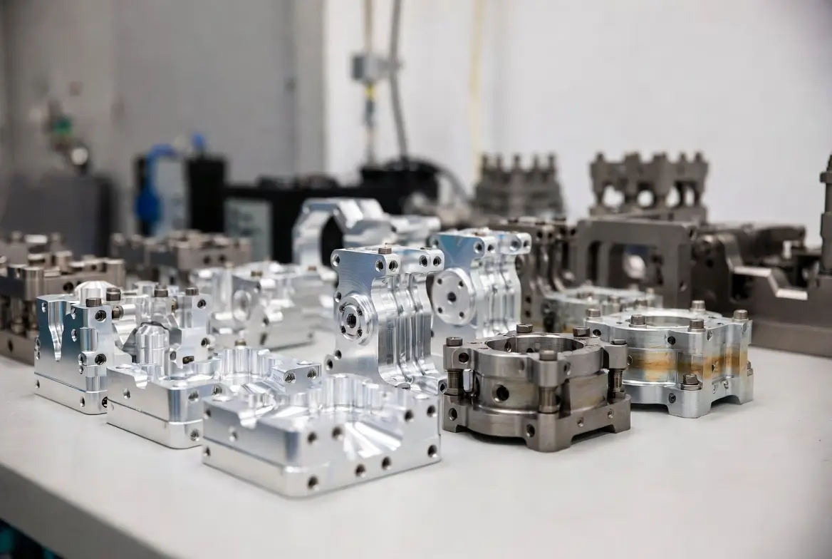
This guide is written specifically for builders who have CNC machining capability. That’s a significant advantage. Most hobbyist humanoid projects are constrained to 3D-printed parts — which limits joint precision, load capacity, and long-term durability. With a CNC machine, you can produce aluminum joint housings with bearing fits measured in microns, machine your own cycloidal gearboxes, and build a robot whose mechanical quality rivals commercial platforms costing tens of thousands of dollars.
This is not a weekend project. A serious humanoid robot takes months of design, machining, wiring, programming, and iterative testing. But this guide will walk you through every phase — from the first design decisions to the first walking steps — with the depth and specificity that actually gets you there.
Let’s build something extraordinary.
Understanding the Complexity Before You Start
Before buying a single component or designing a single part, you need a clear mental framework. Humanoid robots are hard for three reasons stacked on top of each other:
Mechanical: Bipedal walking demands sophisticated balance control that wheeled robots never face
Electrical: Dozens of joints firing simultaneously — current management and signal interference are real problems
Software: Static stability → quasi-static motion → real-time dynamic balance — each step is its own engineering discipline
Realistic goal ladder for beginners:
Phase
Goal
Milestone Movement
Phase 1
Static stability
Stand, move arms, turn head — without falling
Phase 2
Quasi-static motion
Weight shifting, single-leg support
Phase 3
Dynamic walking
Continuous stepping — hardest, tackle last
⚠️ Most first-time humanoid projects fail because builders aim straight for walking and skip Phases 1 and 2 entirely.
Design Planning: Everything on Paper First
2.1 Size Affects Every Decision Downstream
Scale
Height
Advantages
Disadvantages
Small
30–40 cm
Low cost, low torque demand, safe to test
Limited visual impact
Medium
50–80 cm
Balances capability with manageability
Needs mid-range motors
Large
>100 cm
Human-scale, impressive results
High torque demand, expensive, dangerous when it falls
CNC recommendation: Start medium. Parts are large enough that your machining precision becomes a genuine advantage, but not so large that weight spirals out of control.
2.2 Degrees of Freedom — Define This Before Cutting Anything
This is the skeleton of your entire mechanical design. Lock it down before machining a single part:
Head:           2 DOF  →  pan (yaw) + tilt (pitch)
Neck:           1 DOF  →  optional forward lean

Each arm:       7 DOF
  Shoulder:     3 DOF  (flexion / abduction / internal rotation)
  Elbow:        1 DOF  (flexion/extension)
  Wrist:        2 DOF  (flexion / radial-ulnar deviation)
  Forearm:      1 DOF  (pronation/supination)

Torso:          2 DOF  →  forward bend + lateral bend

Each leg:       6 DOF
  Hip:          3 DOF  (flexion / abduction / rotation)
  Knee:         1 DOF  (flexion/extension)
  Ankle:        2 DOF  (plantar-dorsiflexion / inversion-eversion)

Total:          ~30 DOF  (beginner version can trim to 16–20 DOF)
💡 Every DOF you add means one more motor, one more transmission, one more encoder, and hundreds more lines of control code. Cutting unnecessary DOF is a fundamental engineering skill — not a compromise.
2.3 Budget Allocation
Allocate by category upfront so you don’t run out of money halfway through:
Category
Allocation
Notes
Servo / drive motors
40%
Single largest cost
Structural materials (your CNC stock)
20%
Aluminum, bearings, fasteners
Electronics & controllers
15%
MCU, driver boards, sensors
Power system
15%
Battery pack, BMS, DC-DC converters
Tooling, consumables, spare parts
10%
End mill wear, test pieces
A basic humanoid typically runs $500–$2,000 depending on size and capability. Plan for overruns — they always happen.
Component Selection: Motors and Materials
3.1 Servo Motor Selection — Your Most Critical Decision
Digital servos over analog, always. Better precision, stronger position holding, richer feedback.
Torque calculation formula:
Required torque = Load mass × Gravity × Moment arm × Safety factor (1.5–2.0×)
Units: kg × 9.8 m/s² × m = N·m
Convert: 1 N·m ≈ 10.2 kg·cm
Joint torque requirements (30–40 cm robot):
Joint
Torque Needed
Reason
Hip
15–25 kg·cm
Supports full body weight during single-leg stance
Knee
15–20 kg·cm
High load during bending
Ankle
10–15 kg·cm
Critical for balance correction
Shoulder
5–10 kg·cm
Arms are relatively light
Elbow / Wrist
3–8 kg·cm
Low end-effector load
Head
3–5 kg·cm
Head mass is small
⚠️ Undersized servos overheat, drift under load, and fail to complete movements. When in doubt, size up one tier.
Actuation system comparison:
Approach
Example Products
Pros
Cons
Smart bus servos
Dynamixel MX-64, XH540
Plug-and-play, built-in encoder feedback
Expensive
BLDC + planetary gearbox
T-Motor + gearbox
High torque density
Needs external driver
BLDC + cycloidal drive
Self-machined
High ratio, zero backlash
Requires precision CNC
Hollow-core + harmonic drive
Industrial grade
Ultra-precise
Very high cost
3.2 Structural Materials — Where Your CNC Skills Shine
Aluminum alloy comparison:
Grade
Tensile Strength
Machinability
Best For
Notes
6061-T6
310 MPa
★★★★★
Most structural parts
First choice — best value
7075-T6
572 MPa
★★★☆☆
High-stress joints (hip, knee)
Strong but harder to machine
2024-T3
483 MPa
★★★★☆
Fatigue-critical locations
Aerospace grade, fatigue resistant
CNC machining key parameters:
Minimum wall thickness: 2mm for non-structural, 3mm for load-bearing
Bearing bore tolerance: H7 fit — e.g. ø22 H7 = +0 / +0.021mm
Threaded holes: Use Helicoil thread inserts for M3/M4 in aluminum — prevents stripping
Surface treatment: Hard anodize (Type III) — dramatically improves wear resistance at joint interfaces
Weight reduction: Pocket milling — aggressive material removal can reduce part weight 30–50% while maintaining stiffness
Other materials in the build:
Material
Application
Process
Carbon fiber tube
Upper/lower arm links
Buy stock tubes, CNC aluminum end fittings
Stainless steel (304)
Pins, shafts
Turning — sufficient hardness
Brass
Small bushings, threaded inserts
Turning — self-lubricating properties
Delrin (POM)
Small pulleys, cable guides
CNC machinable — lightweight, low friction
Mechanical Construction (CNC Focus)
4.1 Build Sequence
Torso frame → Single leg (validate first) → Both legs → Both arms → Head/neck → Full integration
Do not design everything and then build everything. Build one leg, get it moving, find the problems — this is the fastest path to real progress.
4.2 Torso Machining
The torso is the reference datum for everything else — it must be rigid:
Use a box or frame structure — internal space routes cables, houses the battery, mounts the control boards
Leg attachment faces need parallelism and perpendicularity ≤ 0.1mm — if the two leg mounting planes aren’t parallel, the robot will always lean
Design removable side panels for access to internal electronics during debugging
4.3 Leg Joint Machining — Highest Precision Requirements
Joint design concept:
Motor output shaft → Reduction mechanism → Cross-roller / deep groove bearing → Link arm
CNC machining tolerances for joints:
Feature
Requirement
Why It Matters
Bearing bore roundness
≤ 0.01mm
Bearing installation quality directly affects service life
Joint axis alignment
≤ 0.05mm
Misalignment causes binding and motor overload
Shaft-to-bore fit
H7/p6 interference
Prevents bearing outer race from spinning
Pin joint fit
H7/h6 clearance
Allows rotation with no looseness
Knee-to-ankle axis parallelism
≤ 0.02mm
Both axes must be parallel for clean leg swing
Recommended bearing selection (ø20–30mm joints):
Deep groove ball bearings: 6004 / 6005 — light load, suitable for arms
Cross-roller bearings: RV series — high rigidity, ideal for hip joints
Thin-section bearings: 61800 series — when axial space is tight
4.4 Cycloidal Drive — Advanced CNC Challenge
If your machining capability is strong, a self-machined cycloidal reducer delivers zero backlash and very high torque density:
Eccentricity: e = 1–3mm (smaller values for smaller robots)
Reduction ratio: typically 1:11 to 1:87
Pin wheel hole: roundness ≤ 0.01mm, position tolerance ≤ 0.015mm
These tolerances are fully achievable on a good machining center — but they demand strict control of tooling, spindle speed, and feed rate. Use sharp carbide end mills and dedicate a separate finish pass to all critical features.
4.5 Arms and Head
Arms:
Arms don’t bear body weight — use carbon fiber tube + aluminum end fittings to minimize mass
CNC the end fittings: motor mount flange + bearing housing + threaded holes
Machine integrated cable routing channels through link arms — prevents cables from being pinched by joints
Head:
Mount depth camera (Intel RealSense), ultrasonic sensors, or RGB cameras
Design sensor placement for clear line-of-sight — shoulders and torso must not obstruct the field of view at normal operating poses
Neck cable routing: leave generous slack for the full ±90° rotation range — insufficient slack breaks wires within hours of operation
4.6 Test-Fit Everything Before Final Assembly
Every component must be trial-fitted and verified before permanent fastening.
Pre-assembly checklist:
All joints clear their full range of motion with no mechanical interference
All cables reach their endpoints without excessive tension at any position
Bearings seat squarely — no tilt, no noise on rotation
All threaded fasteners use medium-strength thread locker (Loctite 243) — vibration will loosen everything without it
Electronics Integration
5.1 Wire Before You Wire — Draw the Diagram First
Before connecting anything, create a complete electrical schematic covering:
All power paths: battery → BMS → DC-DC converters → loads
All signal paths: controller → motor drivers → motors
All sensor interfaces
Wire gauge selection:
Current Range
Recommended Gauge
Application
< 1A
28 AWG
Signal lines, sensors
1–3A
24 AWG
Individual servo connections
3–8A
20 AWG
Single axis motor drives
> 8A
16–18 AWG
Main power distribution bus
5.2 Power Architecture
Most important principle: Separate logic power from motor power completely
LiPo Battery Pack (24V main bus)
├── DC-DC Buck → 5V / 3A → MCU, sensors (independently regulated)
├── DC-DC Buck → 12V → cooling fans, auxiliary loads
└── Direct → Motor driver boards (high-current motor path)

Single-point ground tie between logic and power grounds at the source
Why separate them? Motor startup draws large current spikes that cause momentary voltage drops on shared supply lines — this resets microcontrollers and corrupts sensor readings mid-movement.
Capacitor filtering: Add 1000–4700μF electrolytic capacitors across servo power rails to absorb current transients.
Each layer has a clearly defined responsibility and does not reach into the others. This is the fundamental architecture of every serious robotics system — and the reason professional robots are maintainable.
struct Pose {
  int angles[20];  // Angles for all 20 joints
};

void moveToPose(Pose target, int duration_ms) {
  // Incrementally step each joint toward target
  // over duration_ms milliseconds
}
Step 3: Static gait walking logic
① Shift center of mass over left leg (left leg becomes support)
② Lift right leg (right foot clears ground)
③ Swing right leg forward and plant foot
④ Shift center of mass over right leg
⑤ Lift left leg — repeat cycle
Step 4: IMU feedback balance correction
cpp
float pitch = imu.getPitch();
if (abs(pitch) > TILT_THRESHOLD) {
  int correction = (int)(pitch * Kp);
  ankleServo.write(ankleServo.read() + correction);
}
Testing and Iteration
7.1 Test Sequence — Never Skip Steps
Static stand (power OFF) → Static stand (power ON) → Single joint motion
→ Compound poses → Weight shifting → Single foot lift → One step → Continuous walking
Powered-off static stand test: If the robot falls when motors are off, you have a mechanical center-of-mass problem. No software can fix this. Resolve it mechanically first.
7.2 Video Analysis
Record every test session without exception
Review at 0.25× speed — find exactly where balance loss begins
Compare successful and failed attempts — the difference is often millimeters of center-of-mass shift or milliseconds of timing error
7.3 What Good Iteration Looks Like
Fix one problem at a time, retest, verify the fix worked, then move to the next issue. This sounds obvious but almost no one does it. The instinct is to fix everything at once — which makes it impossible to know which fix worked. Methodical single-variable testing produces measurable, compound progress.
Common Problems and Solutions
Symptom
Root Cause
Fix
Motors overheating
Insufficient torque / mechanical binding
Upgrade motors / check joint freedom
Robot always leans to one side
Center of mass off centerline
Reposition battery / add counterweight
Servo jitter and instability
Voltage sag under load
Increase wire gauge / add filter capacitors
Joint backlash (slop)
Transmission play
Switch to harmonic/cycloidal drive / preload bearings
Controller resets during movement
Motor noise on shared power supply
Fully separate logic and motor power
Wires cut by joints
Insufficient cable slack at joints
Redesign routing channels, add protective conduit
Expansion Roadmap
Once the base robot is stable:
Voice control       →  Speech recognition (XMOS / Google Coral) + command parsing
Computer vision     →  Object detection (YOLOv8 on Jetson) + manipulation targeting
Wireless telemetry  →  WiFi / Bluetooth + real-time data dashboard
Advanced motion     →  Full IK solver + real-time trajectory planning
ML gait learning    →  Reinforcement learning (MuJoCo sim → real hardware transfer)
Summary — Your CNC Advantage
As a CNC machinist entering humanoid robotics, you hold three advantages that most builders simply don’t have:
1. Joint precision far beyond 3D printing → Bearing fits are correct, motion is smooth, wear life is long
2. You can manufacture your own reducers → Self-machined cycloidal or planetary gearboxes at a fraction of commercial cost
3. Full material freedom → 6061 aluminum is 5–10× stronger than PLA and dimensionally stable under both load and heat
Start with one leg. Get it moving. Validate the kinematics, the joint tolerances, the torque margins — then build the second. This is the fastest path to a working robot and the fastest way to surface problems before they multiply across the whole system.
Ryan Wang is the CNC Machining Expert at Cncpioneer, with over 15 years of hands-on experience as a CNC programmer, process engineer, senior machinist, and precision manufacturing specialist. He has helped companies in aerospace, automotive, medical, and electronics sectors achieve micron-level tolerances and scale from prototypes to high-volume production. Ryan is also an experienced instructor in advanced CNC techniques, particularly five-axis machining and challenging materials.