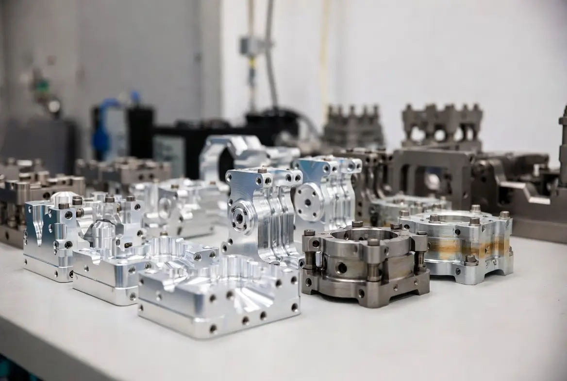
In 2026, robotics is no longer confined to automotive assembly lines or research labs. Collaborative robots (cobots), humanoid platforms, warehouse AMRs, surgical robots, and consumer service bots are all scaling rapidly — and almost every one relies on CNC machined robotic parts for structural integrity, precision joints, lightweight frames, and repeatable motion.
CNC machining of robot parts remains the gold standard subtractive method when tolerances tighter than ±0.01 mm, complex geometries, or production volumes between 10 and 5,000 pieces are required. 3D printing handles prototypes and lattice structures well, but when strength-to-weight ratio, surface finish, and metal fatigue life matter most — especially in articulated joints, end-effectors, gearboxes, and sensor housings — CNC robot parts still dominate.
Whether you’re a robotics startup designing the next-generation cobot arm, an OEM scaling humanoid production, or an engineer iterating on an industrial pick-and-place system, understanding how cnc machining robotic parts works will save you months of redesigns and thousands in scrap.
Why Robot Parts Demand CNC Machining
Robotic components face extreme and often contradictory requirements:
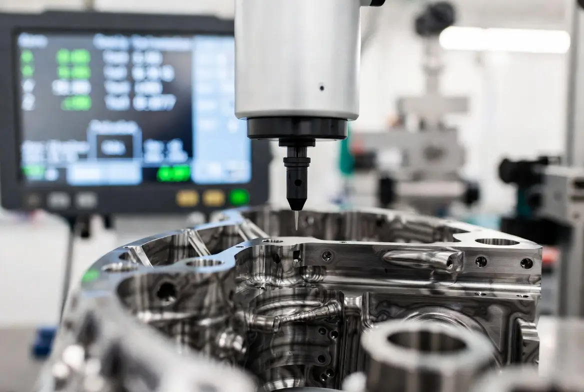
- Ultra-tight tolerances — encoder mounts, harmonic drive interfaces, and bearing bores routinely require ±0.005 mm to ±0.015 mm.
- High stiffness-to-weight — arms and links must resist deflection while minimizing inertia.
- Wear resistance & fatigue life — joints cycle millions of times.
- Complex free-form geometry — curved housings, organic joint shapes, integrated cable channels.
- Multi-material compatibility — anodized aluminum bodies mated to stainless steel shafts or titanium fasteners.
Additive manufacturing excels at organic shapes but struggles with consistent mechanical properties in metals and anisotropic strength. Casting or forging can be cost-effective at 10,000+ units, but tooling lead times and minimum order quantities make them impractical for most robotics companies in 2026.
That leaves CNC machining — especially 3+2 axis and full simultaneous 5-axis CNC machining robotic parts — as the most reliable bridge between prototype and mid-volume production.
Most Common Materials for CNC Machined Robot Components
| Material | Typical Robot Applications | Key Advantages | Typical Tolerance | Cost Level |
|---|---|---|---|---|
| 6061 / 7075 Aluminum | Arms, frames, housings, brackets | Lightweight, excellent machinability, anodizing | ±0.01 mm | $ |
| 7075-T6 Aluminum | High-stress links, gearbox housings | Highest strength-to-weight in aluminum family | ±0.005–0.01 mm | $$ |
| 304 / 316 Stainless | Shafts, fasteners, food-grade / medical parts | Corrosion resistance, durability | ±0.01 mm | $$$ |
| 17-4PH / 15-5PH | High-load joints, surgical robot components | Precipitation hardening, very high strength | ±0.005 mm | $$$$ |
| Titanium (Grade 5) | Lightweight high-end humanoid joints | Best strength-to-weight + biocompatibility | ±0.01 mm | $$$$ |
| POM (Delrin) / PEEK | Bushings, gears, low-friction sliding surfaces | Self-lubricating, dimensional stability | ±0.02 mm | $$ |
Pro tip (2026): Many robotics teams now specify mic-6 aluminum cast plate or durabar for large flat structural plates because of guaranteed flatness and low internal stress after machining.
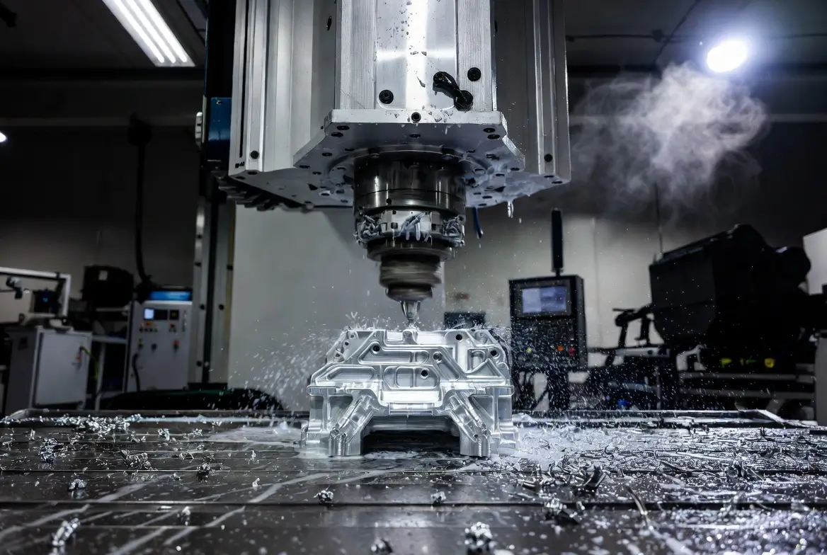
Key CNC Processes Used for Robotics Parts
Modern shops use these workflows for cnc machined robotic parts:
- 3-axis milling — simple brackets, plates, covers
- 3+2 axis (indexed 5-axis) — most cost-effective for 80% of robot joints and links
- Simultaneous 5-axis — undercuts, deep cavities, organic joint shapes, impeller-like end-effectors
- Turn-mill (mill-turn) — shafts with milled flats, threads, and keyways in one setup
- Swiss-type turning — very small-diameter precision pins and standoffs (< Ø20 mm)
Video: Real-world 5-axis + turning on humanoid robot components (Shows multi-process integration on frames, joints, and shells — highly relevant to current humanoid scaling.)
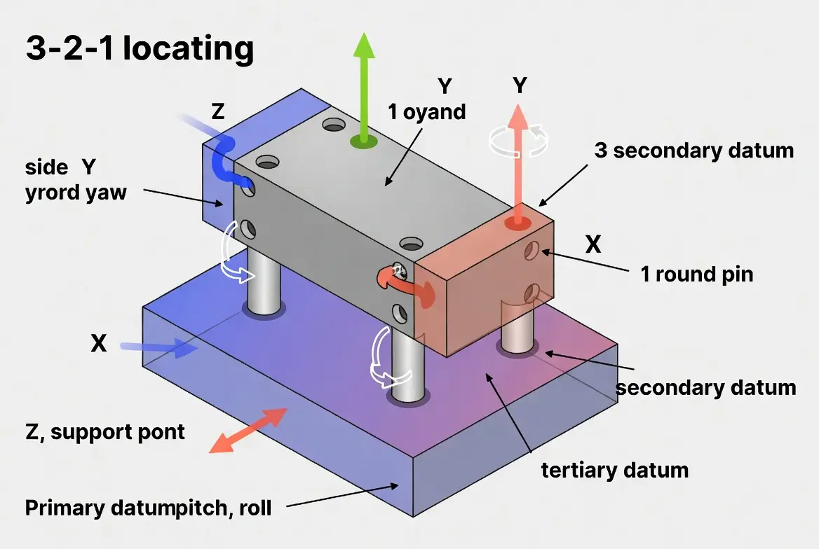
Design & Tolerancing Considerations for Robotic Parts
- Use GD&T correctly: position, perpendicularity, and profile tolerances over coordinate dimensions whenever possible.
- Avoid deep pockets with thin walls (< 1.2–1.5 × tool diameter) unless using 5-axis or high-speed machining.
- Design for fixturing: add witness faces, dowel holes, or machining tabs.
- Plan for material certification and coating compatibility early (especially passivation + anodizing stacks).
- Simulate thermal expansion in joints — aluminum expands ~2× more than steel.
Video: Full 5-axis process on an intricate robot gear (university robotics project) (Demonstrates tight-tolerance complex geometry — excellent reference for designers.)
Frequently Asked Questions
Q1: What is the typical tolerance for CNC machining robot parts?
A: ±0.01 mm is standard; ±0.005 mm or better is common on critical features (bearing bores, dowel holes) with 5-axis and proper fixturing.
Q2: Is 5-axis CNC always necessary for robotic components?
A: No — about 60–70% of parts can use 3+2 indexing. True simultaneous 5-axis is reserved for undercuts, deep cavities, or organic shapes.
Q3: Aluminum vs titanium for robot arms — which is better in 2026?
A: 7075 aluminum + hard anodizing wins 80% of applications for cost/weight. Titanium is chosen when weight savings justify 3–5× material cost or when biocompatibility is required.
Q4: How many pieces justify moving from 3D printing to CNC machining?
A: Usually 10–30 pieces, depending on geometry. Beyond 50–100 pieces, CNC almost always wins on mechanical properties and surface finish.
Q5: Can you combine CNC with other processes for robot parts?
A: Yes — hybrid workflows (CNC + laser marking + passivation + assembly + wiring) are now standard among top suppliers.
Ready to Start Your Robot Parts Project?
Whether you need 10 prototype joints or 2,000 mid-volume links, the right CNC partner can cut weeks off your timeline and thousands off your budget.
Get a fast, no-obligation quote today — upload your STEP/IGES files and we’ll respond within 24 hours.

Ryan Wang
Ryan Wang is the CNC Machining Expert at Cncpioneer, with over 15 years of hands-on experience as a CNC programmer, process engineer, senior machinist, and precision manufacturing specialist. He has helped companies in aerospace, automotive, medical, and electronics sectors achieve micron-level tolerances and scale from prototypes to high-volume production. Ryan is also an experienced instructor in advanced CNC techniques, particularly five-axis machining and challenging materials.