Precision aerospace CNC machined parts play a critical role in modern aircraft, satellites, rockets, and unmanned aerial vehicles. These components must deliver exceptional strength-to-weight ratios, survive extreme thermal cycling, vibration, and pressure, and meet rigorous safety and performance standards [1]. In an industry where failure is not an option, CNC machining—particularly 5-axis simultaneous milling and mill-turn processes—has become the preferred subtractive manufacturing method for producing complex, high-precision geometries with repeatable accuracy.
This guide provides a comprehensive overview of precision aerospace CNC machining. It examines core technical requirements, material selection, functional classification of parts, tolerance and quality standards, design-for-manufacturability (DFM) principles, full process workflows, and emerging trends. The information draws from established industry standards, peer-reviewed research, and authoritative technical publications, enabling engineers, designers, and procurement professionals to make informed decisions when specifying or sourcing aerospace components.
What is Precision Aerospace CNC Machining
Aerospace components demand tolerances far tighter than those typical in general manufacturing. Structural airframe parts commonly require ±0.0127 mm, while engine and hydraulic elements often call for ±0.005 mm or better, with critical sealing surfaces reaching ±0.001 mm [1]. These specifications eliminate vibration-induced fatigue, ensure aerodynamic efficiency, and maintain perfect fit across assemblies.
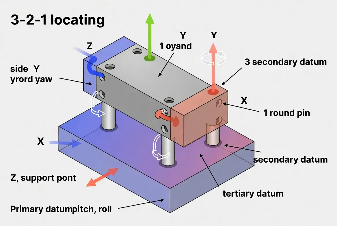
Five-axis simultaneous CNC machining has become essential. Unlike traditional 3-axis setups that require multiple fixturing operations and introduce cumulative error, 5-axis centers produce complex airfoils, deep pockets, and undercuts in a single setup. This approach minimizes fixture-induced distortion and improves surface continuity, which is particularly valuable for turbine blades and satellite antenna mounts. Palletized systems further support high-mix, low-volume production typical of satellite and prototype programs.

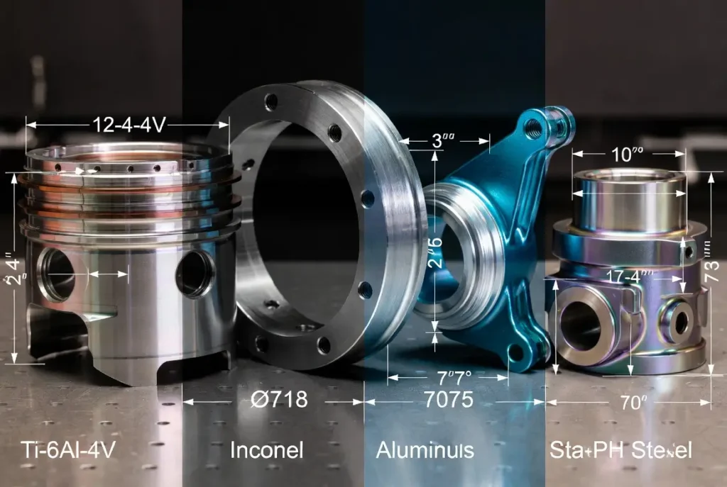
Common Aerospace-Grade Materials and Selection
Material selection directly influences weight, heat resistance, corrosion performance, and machinability. The table below summarizes the primary alloys used in 2026 aerospace applications, based on mechanical property data from industry standards.
| Material | Strength-to-Weight Ratio | Max Operating Temp (°C) | Machinability Rating (1–10) | Typical Applications | Relative Cost |
|---|---|---|---|---|---|
| Aluminum 7075-T651 | Excellent | 120 | 9 | Wing spars, brackets, fuselage frames | Low |
| Aluminum 6061-T6 | Good | 150 | 10 | Non-structural housings, panels | Lowest |
| Titanium Ti-6Al-4V | Outstanding | 400 | 5 | Landing-gear pistons, engine mounts | High |
| Inconel 718 | Very High | 700 | 4 | Turbine disks, compressor cases | Very High |
| Inconel 625 | High | 980 | 4 | Rocket nozzles, exhaust ducts | Very High |
| Stainless Steel 17-4PH | High | 300 | 7 | Hydraulic valve bodies, actuators | Medium |
| PEEK (high-performance plastic) | Good | 250 | 8 | Electrical insulators, sensor housings | Medium-High |
Engineers should finalize alloy grade and heat-treat condition early in the design phase. Titanium and nickel-based superalloys require rigid machine setups, coated carbide tooling, and high-pressure coolant strategies to counteract work hardening and excessive heat generation [3].
Tolerances, Surface Quality, and Quality Systems
Industry-standard tolerance bands for aerospace CNC parts include:
- Structural/airframe components: ±0.0127 mm
- Engine and gearbox elements: ±0.005 mm
- Hydraulic and fuel manifolds: ±0.0025 mm
- Critical sealing surfaces: ±0.001 mm or tighter
Surface finishes are equally important—Ra 0.8 µm for aerodynamic surfaces and Ra 0.4 µm for sealing faces. All manufacturing must comply with AS9100D quality management systems, Nadcap accreditation for special processes (heat treatment, nondestructive testing, and coatings), and AS9102 First Article Inspection (FAI) requirements [1][2]. Full material traceability is achieved through mill test certificates (MTCs), serialized marking, and digital batch records.
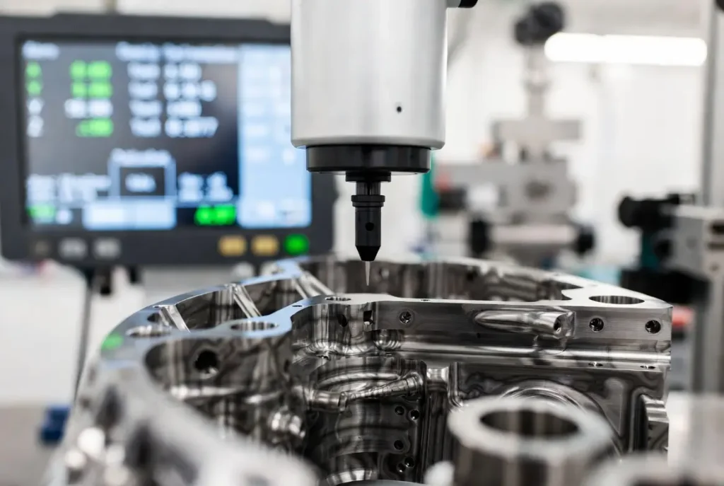
Inspection relies on coordinate measuring machines (CMM) with 0.001 mm repeatability, laser scanners, in-process probing, and Nadcap-approved nondestructive testing methods such as fluorescent penetrant inspection, X-ray, and ultrasonic examination.
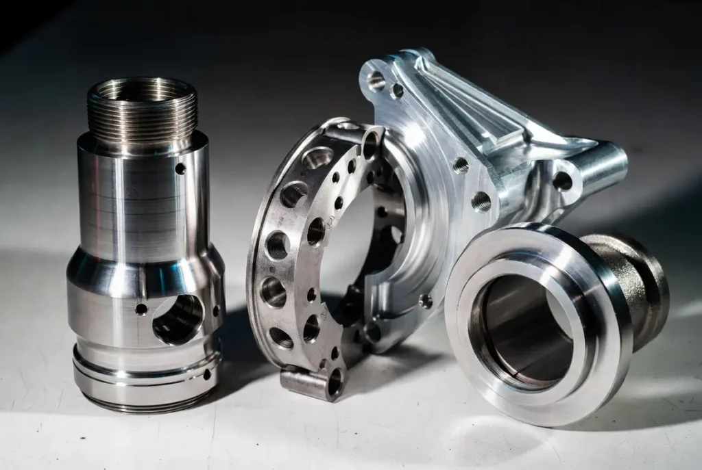
Types of Precision Aerospace CNC Machined Parts
Aerospace components are systematically classified by functional system. This classification guides material choice, tolerance allocation, and process selection.
Airframe and Structural Components
These load-bearing elements form the aircraft skeleton while minimizing weight. Common parts include wing spars, ribs, bulkheads, fuselage frames, stringers, mounting brackets, and fairings. Primary materials are aluminum alloys (7075-T651, 2024-T3) and titanium. Tolerances typically range from ±0.0127 mm to ±0.025 mm, with true-position requirements under 0.05 mm. Five-axis machining enables monolithic designs that reduce fastener count and associated fatigue risks.
Engine and Propulsion Components
Operating under extreme temperatures and rotational speeds, these parts include turbine disks, compressor cases, nozzle segments, and fuel injectors. Nickel-based superalloys such as Inconel 718 dominate. Airfoil profiles require ±0.005 mm tolerances and Ra 0.4–0.8 µm finishes [4]. The low machinability of superalloys necessitates 5-axis strategies to produce complex internal cooling channels without distortion.
Landing Gear and Actuation Components
Aerospace Connector PinsThese elements withstand high-impact loads. Struts, pistons, cylinders, and actuator housings are typically machined from titanium or high-strength stainless steel. Bore and outer-diameter tolerances reach ±0.0025 mm, with concentricity under 0.005 mm. Deep-hole gun drilling and mill-turn centers ensure fatigue life and hydraulic sealing integrity.
Hydraulic, Fuel, and Fluid System Components
Manifolds, valve bodies, and fittings handle pressures up to 5,000 psi. Materials include aluminum and stainless steel. Port locations and sealing faces require ±0.002 mm accuracy. Five-axis and EDM-assisted machining minimize leak paths by producing intricate intersecting passages in a single setup.
Flight Control and Empennage Components
Actuator housings, bell cranks, and hinge fittings demand kinematic precision. Tolerances focus on hinge-line alignment (±0.01 mm) and parallelism (<0.008 mm). Aluminum and titanium are common.
Avionics, Sensor, and Electronic Enclosures
Chassis and heat sinks protect electronics from vibration and EMI. Aluminum alloys provide thermal conductivity and shielding. Connector alignment tolerances are typically ±0.01 mm.
Satellite, Spacecraft, Rocket, and UAV Components
Antenna mounts, bus structures, and payload brackets emphasize extreme lightweighting and thermal stability. Materials include aluminum, titanium, and low-expansion alloys such as Invar. Alignment features for optical payloads often require ±0.005 mm tolerances.
This functional classification helps engineers allocate tolerances and select suppliers with appropriate process capabilities.
Aerospace-Grade DFM Design Suggestions
Effective design-for-manufacturability reduces cost and lead time while maintaining performance. Ten key guidelines include the following:
- Specify tight tolerances only where functionally required.
- Incorporate generous fillets (minimum radius 0.5 mm) to reduce stress concentrations.
- Avoid deep, narrow cavities (depth-to-diameter ratio >6:1) in titanium.
- Plan heat-treatment sequences early to control distortion.
- Align datum features for single-setup 5-axis machining.
- Prefer standard tool diameters to avoid custom tooling.
- Design for serialized marking and inspection access.
- Account for spring-back in thin-wall aluminum components.
- Minimize unsupported thin walls (<1.5 mm) in high-temperature alloys.
- Conduct a supplier DFM review before freezing the design.
Full Processing Workflow and 2026 Trends
A typical workflow begins with CAD/CAM programming, followed by 5-axis roughing, semi-finishing, heat treatment, finish machining, surface treatment, 100% inspection, FAI, and digital certificate of conformance packaging.
Emerging 2026 trends include AI-driven adaptive tool-path optimization (reducing cycle times by 15–25%), hybrid additive–subtractive manufacturing for internal cooling channels, digital twins for real-time quality monitoring, and sustainable closed-loop coolant systems [6].
Frequently Asked Questions
What is the minimum order quantity for satellite or UAV parts?
AS9100-certified facilities routinely produce prototypes (1–5 pieces) and small batches (10–200 pieces).
What distinguishes AS9100 from ISO 9001?
AS9100 incorporates aerospace-specific requirements for configuration management, risk mitigation, and counterfeit-part prevention.
What is a typical lead time for titanium components?
Four to eight weeks from purchase order to shipment, depending on complexity and heat-treatment requirements.
What files are needed for accurate quoting?
STEP or native CAD models, 2D drawings with GD&T, material specifications, and quantity.
Summary
Precision aerospace CNC machined parts represent the convergence of advanced engineering demands and high-accuracy subtractive manufacturing. By understanding material properties, tolerance requirements, functional classifications, and DFM principles, designers and manufacturers can achieve reliable, flight-ready hardware that meets the stringent demands of aviation, space, and defense applications. Selecting processes and partners based on these technical considerations helps accelerate development, control costs, and ensure compliance with global aerospace standards.
References
[1] SAE International. AS9100D: Quality Management Systems – Requirements for Aviation, Space, and Defense Organizations. Available at: https://www.sae.org/standards/content/as9100d/
[2] Performance Review Institute (PRI). Nadcap Accreditation Program for Aerospace Manufacturing Special Processes. Available at: https://www.p-r-i.org/nadcap
[3] Ezugwu, E. O., & Wang, Z. M. “Titanium Alloys and Their Machinability—A Review.” Journal of Materials Processing Technology 68, no. 3 (1997): 262–274. Available at: https://www.sciencedirect.com/science/article/pii/S0924013696000301
[4] NASA. Additive Manufacturing of Aerospace Propulsion Components. NASA Technical Reports Server, 2015. Available at: https://ntrs.nasa.gov/api/citations/20150023067/downloads/20150023067.pdf
[5] Deloitte. 2026 Aerospace and Defense Industry Outlook. Deloitte Insights, November 2025. Available at: https://www.deloitte.com/us/en/insights/industry/aerospace-defense/aerospace-and-defense-industry-outlook.html