
MULTI-FACE STRUCTURE
Structural Components
Open sections, mounting faces and bores require a planned approach to workholding and feature relationships.
COMPLEX GEOMETRY · CONSIDERED MACHINING
Angled features, contoured surfaces and multi-face components need a machining plan built around the drawing. We review tool access, workholding and the dimensions that matter. Examples to review include multi-face mechanical parts and components used in robotic machining cells.
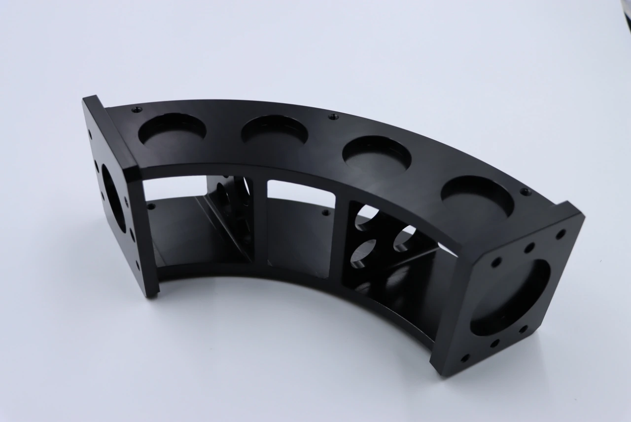
*The suitable route and machine configuration are confirmed against the part and equipment requirements.
Five-axis machining expands access to angled and multi-face features. Whether indexed or simultaneous motion is appropriate depends on the drawing, setup and available machine configuration.
POSITION. LOCK. MACHINE.
Two rotary axes position the part or tool. The orientation stays fixed while the three linear axes machine the feature.
A practical route when each feature can be machined at a fixed tool orientation.
COORDINATED MOTION
Linear and rotary axes move together during cutting to follow a surface or maintain a suitable tool approach.
The machining route depends on tool access, machine configuration, programming and the part requirements.
Use the process the part needs. If three-axis machining can meet the drawing efficiently, it may be the more practical route.
Compare 3-Axis Machining02 / PART GEOMETRY
These factory portfolio photographs illustrate part geometry. The machining route and specifications are reviewed for each drawing.
MULTI-FACE STRUCTURE
Open sections, mounting faces and bores require a planned approach to workholding and feature relationships.
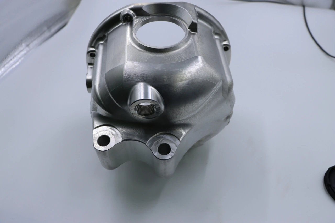
CONTOURED GEOMETRY
Curved surfaces and angled interfaces bring tool access and drawing datums into the same review.
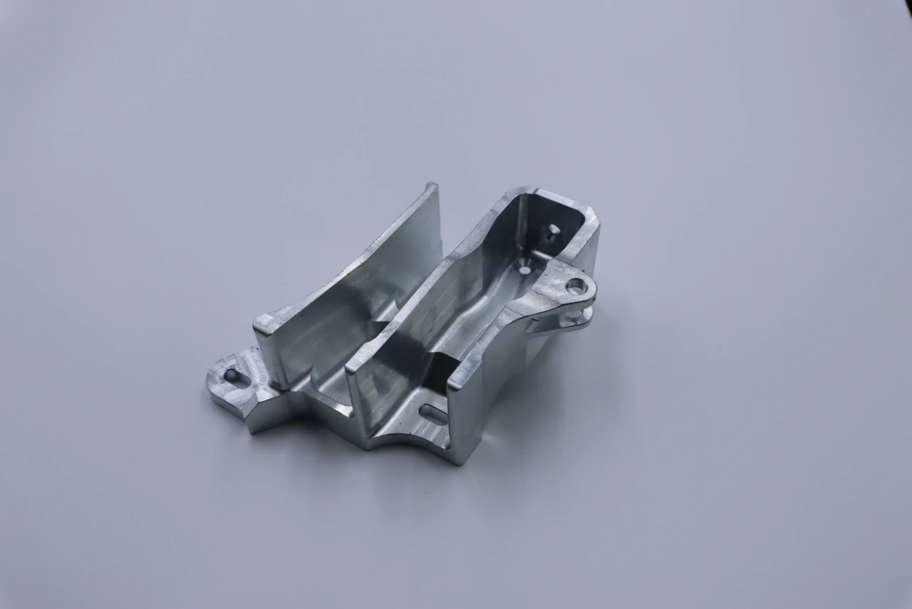
MULTI-FACE MOUNTING
Pockets, tabs and holes across multiple faces can benefit from a coordinated setup sequence.
Representative factory part photographs; individual five-axis operations and tolerances are not attributed to these examples.
03 / ENGINEERING & QUALITY
Plan the datum scheme, workholding and tool access before machining; agree the inspection scope against the dimensions that control function.
Identify the datum system, mating surfaces, bore relationships and dimensions that control the assembly.
Review tool reach, collision clearance, clamping surfaces and the sequence for features that cannot be reached in one setup.
Prepare the toolpath, check the machining sequence and inspect a first article before moving into the agreed production run.
Use the inspection methods agreed for the drawing. Check parts through production and complete final inspection before packing.

INSPECTION EQUIPMENT & RECORDS
CMM, optical projector and height gauge support incoming, first-article, in-process and outgoing checks. Inspection records are retained for three years. Confirm report requirements with your quotation.
Choose a material grade, then specify the finish, appearance and dimensions that matter for your part.
| Material | Available Grades |
|---|---|
| Aluminum | 6061 · 7075 · 2024 · 5052 |
| Stainless Steel | 303 · 304 · 316 / 316L · 17-4PH |
| Carbon & Alloy Steel | 45 Steel · 40Cr · 4140 · 4340 |
| Brass | C360 |
| Copper | C110 · C101 |
| Titanium | Grade 2 · Grade 5 (Ti-6Al-4V) |
| Tool & Mold Steel | P20 · H13 · A2 · D2 |
| Material | Available Grades |
|---|---|
| POM / Acetal | POM · Selected Delrin grades |
| Nylon / PA | PA6 · PA66 |
| Other Engineering Plastics | ABS · PC · PMMA · HDPE · PTFE |
| High-Performance Plastics | PEEK · PEI / ULTEM |
FINISH OPTIONS
Finish availability depends on material and part requirements.
Confirm coating thickness, masked areas and whether critical dimensions apply before or after finishing.
Answers to common engineering and sourcing questions.
In indexed 3+2 machining, the rotary axes position the part or tool and remain fixed while cutting takes place along the linear axes. In simultaneous 5-axis machining, linear and rotary axes move together during the cut. The appropriate route depends on the geometry, tool access and available machine configuration.
No. The fixture must hold the part, so clamped surfaces and inaccessible features can require another setup. The benefit is often fewer repositioning operations, rather than a guarantee that every part is completed in one setup.
No. Fewer setups can help preserve relationships between features, but accuracy also depends on the material, workholding, tool reach, thermal conditions and inspection method. We confirm tolerances feature by feature against your drawing.
If the required features are accessible in practical setups and the drawing can be met, 3-axis machining may offer a simpler and more economical route. Five-axis machining is considered when added tool access or reduced repositioning provides a useful benefit.
Send the exact material grade and condition with your drawing. Options include aluminum, stainless and alloy steels, titanium and engineering plastics. Finishes are selected for material compatibility and may include anodizing, hard anodizing, bead blasting, polishing, brushing, passivation, electroless nickel plating, zinc plating, powder coating or black oxide.
Include a 3D model, dimensioned drawing, material grade, quantity, drawing revision, required finishes and delivery target. Identify critical tolerances, datums, cosmetic surfaces and the inspection documentation you need. The quotation confirms the machining route, achievable requirements and production schedule.
START WITH YOUR DRAWING
Send your model and requirements for a review of process, material, inspection and production timing.