
CNC Machining Robot Parts: The Complete Guide
Explore machining processes, part categories, and design considerations for robotic assemblies.
CNC machined robot joint housings, arm links, shafts, end-effector hardware, and sensor interfaces for industrial, collaborative, and mobile robot assemblies.
Get Instant QuoteShare drawings for joint housings, links, shafts, and end-effector interfaces. Review bearing seats, locating datums, cable paths, and access for assembly.
Evaluate fit, alignment, stiffness, and component weight in prototype assemblies. Use inspection feedback to refine the next mechanical design revision.
Coordinate mating components under controlled revisions. Agree material, finishing, inspection, and packaging so repeat sets can be assembled consistently.

Ultra-precise, small-diameter complex parts machined from bar stock in a single setup with micron-level tolerances.

Live tooling combines lathe and mill capabilities for cylindrical features, housings, fixtures, and precision assemblies.
Drawing Verification
Measure bearing bores, locating faces, shaft fits, and joint interfaces from a common datum plan to control assembly alignment.
Production Validation
Review sample housings, links, and interface parts together where their dimensional relationships affect motion or assembly.
Traceability Planning
Define material identification and revision records for each component in the robotic assembly, including finishing allowances and mating part references.
Surface & Assembly
Specify burr removal around cable routes, finish on sliding or bearing interfaces, and any assembly checks required by the robot design.
Choose materials around mass, stiffness, joint loading, wear, and the operating environment of the robot.
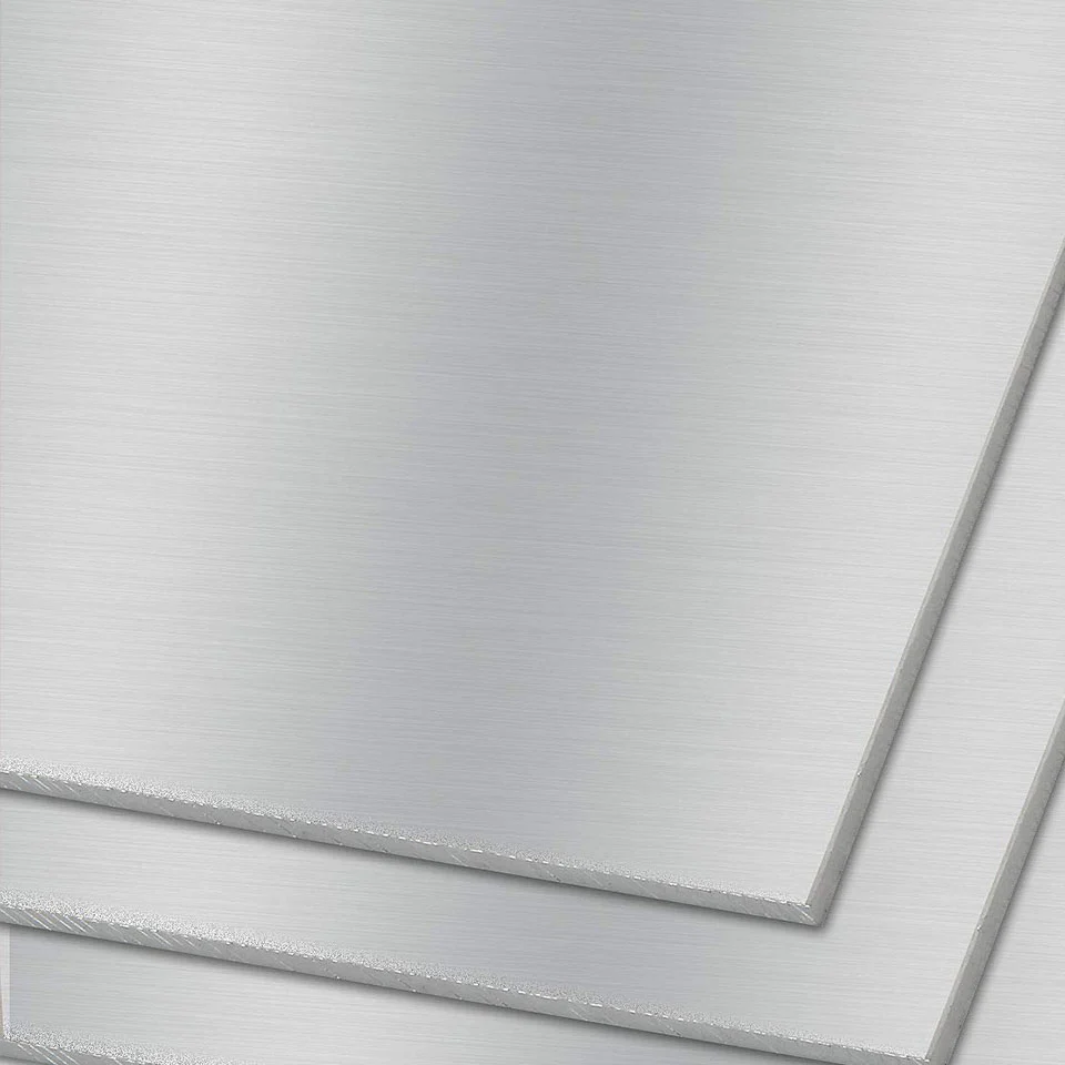
Lightweight
6061 / 7075
Aluminum is a candidate for robot links, covers, joint housings, and other weight-sensitive structural components.
Load & Wear
4140 / 42CrMo as specified
Alloy steel may be specified for shafts, pins, and load-bearing mechanical interfaces.

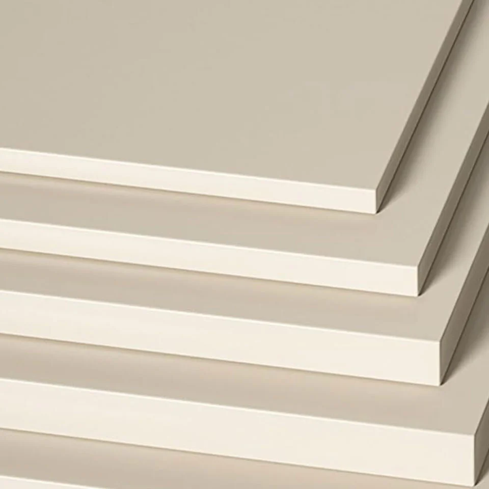
Insulation & Weight
PEEK / POM as specified
Engineering plastics can support lightweight guiding, insulating, and wear-related functions within robot assemblies.
Representative parts for robot joints, structural links, sensing interfaces, and end-of-arm tooling.
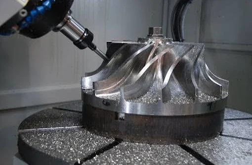
Explore machining processes, part categories, and design considerations for robotic assemblies.
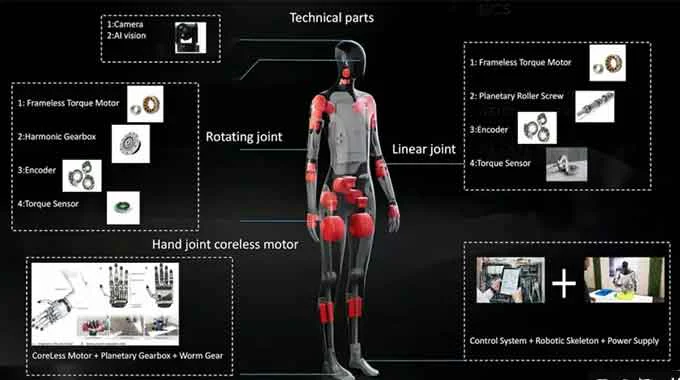
Review structural, joint, and assembly considerations for CNC machined humanoid robot components.
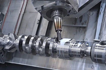
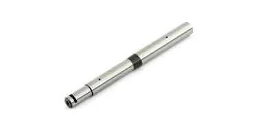
Learn how shaft geometry, material selection, and inspection affect fit and repeatability.
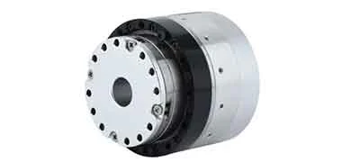
Bearing housings, shafts, and drive-interface hardware depend on relationships between mating features. Define datums, bore and journal requirements, and the inspection method needed to evaluate the assembled joint.
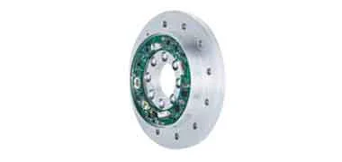
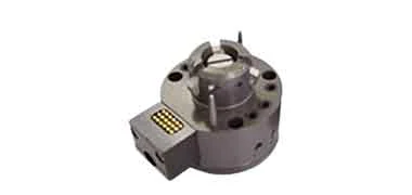
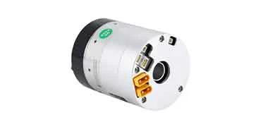
Torque-sensor bodies, encoder mounts, gripper fingers, and tool-changer hardware combine sensing or gripping features with cable access and mounting interfaces. Identify sensor-beam geometry, encoder locating bores, gripper guide fits, and coating masks on the drawing; agree CMM or bore measurement records for critical features.
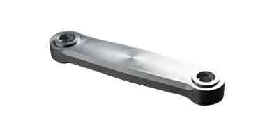
AMR drive hubs and mobile robot chassis parts combine motor mounting faces, encoder bores, wheel interfaces, and cable routes. Collaborative robot arm links may include tube insertion bores and joint attachment flanges. Review locating datums, component mass, mating materials, and environmental protection for the complete assembly.
Plan repeat production for harmonic-drive components, joint bearing housings, AMR drive hubs, collaborative-robot housings, and structural fittings. Review the component family, annual demand, release quantities, and required records before committing to a production schedule.
Provide controlled drawings, mating-part references, forecast quantities, and delivery dates. Review machining setups, fixtures, material availability, and finishing allowances for each component family. Use prototype and first-article feedback to agree the production revision.
Agree critical characteristics such as bearing fits, bore alignment, shaft journals, and mounting interfaces. Define gauges, measurement-system checks, sampling or full inspection, and any SPC or process-capability study needed for the order. Confirm PPAP or FAIR scope where requested.
Link material lots, drawing revisions, machining and finishing records, and inspection results to each delivery batch. Agree release quantities, packaging for precision interfaces, change notification, and replenishment dates so repeat part sets support the customer’s assembly schedule.
Identify the critical diameters, form, and datum relationships on the drawing. Agree suitable dimensional or form measurement methods during review; component measurements alone do not establish complete robot positioning performance.
Use a controlled revision for each build and record design changes after assembly trials. Review first-article results and finishing allowances before releasing repeat production.
Consider wear at contact interfaces, corrosion exposure, electrical grounding, and optical reflection around vision systems. Specify coating thickness and masked surfaces wherever the finish affects fit or function.
Provide the drawing revision, CAD model, material and finish, annual forecast, quantity per release, delivery schedule, and inspection requirements. Highlight mating features and part families that must be supplied together. Capacity, pricing, and lead time are confirmed for the specific program.
Agree a first-article review and a control plan for drawing-critical features. Specify measurement methods, inspection frequency, traceability, and any process-capability study. Capability targets and full-inspection requirements must be validated for the particular geometry and process.
Yes. Submit the assembly drawing and individual part drawings for arm links, joint hardware, drive hubs, sensor bodies, or end-effector components. Identify mating parts, common datums, cable paths, mass limits, and finish allowances. Confirm the inspection and material records required for each part number before manufacture.
Request a release schedule with forecast demand, batch sizes, packaging, and required documentation. Material procurement, production slots, replenishment timing, and drawing-change handling are reviewed before the delivery plan is accepted.
INDUSTRY COMPONENTS
Share the part drawing, material, quantity and application requirements for a project-specific review.