
Drawing-Based Project Review
Review the gear box layout, critical geometry and supplied parts together, so the manufacturing plan follows the approved design and equipment interfaces.
Custom harmonic drive gear box projects for robot joints and precision positioning systems. Share your reduction ratio, torque, speed and installation requirements for a quotation covering the agreed geometry, materials and supply scope.
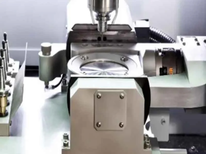
A harmonic drive gear box uses strain wave gearing to transmit motion through a wave generator, flexspline and circular spline. These elements work together within the selected housing, bearing and mounting arrangement.
A custom project starts with the required reduction ratio, torque, input speed and available installation space. Motor connections, output flanges, bearing seats and cable routing must fit the surrounding equipment. The quotation defines the parts, assembly work and inspection records included in the order.

Plan the gear box around its motion requirements, mating interfaces, manufacturing route and inspection scope.
Review the gear box layout, critical geometry and supplied parts together, so the manufacturing plan follows the approved design and equipment interfaces.
Plan machining datums around bearing seats, registers, mounting faces and shaft interfaces. Define the relationships that matter to the assembled gear box.
Review flexspline wall sections, workholding and machining allowances before production. Keep gear geometry and heat-treatment requirements linked to the part drawing.
Specify material grades, treatment conditions and finishing allowances for each part. Protect gear teeth, bearing fits and mounting interfaces during the finishing process.
Use prototype drawing revisions and inspection results to review fit and integration before repeat production. Confirm quantities, packaging and delivery requirements with the quotation.
Identify the dimensional checks, material records and any assembly tests needed for release. Agree acceptance limits and reporting requirements before placing the order.
Explore the gear elements and mounting parts used in a custom gear box project. Define the required supply scope with your enquiry.
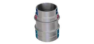
The wave generator transfers input motion to the strain wave gear mechanism. Define its cam profile, shaft connection, bearing interface and inspection datums on the drawing.
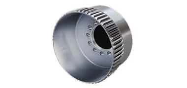
Cup-style flexsplines form the flexible gear element in the selected design. Specify wall geometry, tooth features, hub dimensions and material condition for the mating gear set.
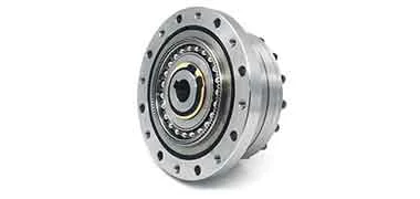
Hat-style flexsplines provide a different mounting arrangement for the gear box layout. Review flange geometry, available axial space and the connections to surrounding parts.

The circular spline is the rigid gear ring that engages the flexspline. Define its internal tooth geometry, locating register and mounting pattern with the required inspection criteria.
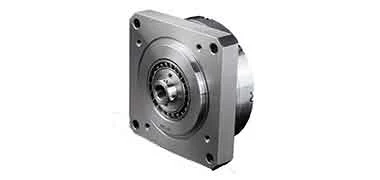
Output flanges and bearing seats connect the gear mechanism to the driven assembly. Specify fits, face relationships, bolt patterns and any hollow passage required by the design.
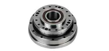
Custom adapters join the gear box to a motor, robot joint or positioning stage. Define locating features, mounting faces and access for fasteners, cables and maintenance.
Custom harmonic drive gear box applications for robot joints, medical positioning and semiconductor motion systems.

Custom harmonic drive gear box solutions for humanoid, collaborative and industrial robot joints. Review reduction ratio, torque, mounting interfaces and output bearing requirements for the assembly.
Explore robotics machining
Harmonic drive gear box applications in surgical robot joints and precision positioning mechanisms. Define installation space, motion requirements and inspection criteria for the equipment.
Explore medical machining
Harmonic drive gear box applications in wafer handling robots and precision rotary positioning mechanisms. Review mounting geometry, motion requirements and equipment integration interfaces.
Explore semiconductor machiningMaterials
Specify materials for each gear element, housing and mounting part, including heat treatment and finishing requirements.
Option for drawing-specified shafts, flanges and structural parts. Define heat-treatment condition, strength requirements and finishing allowances for each part.
Option for specified bearing and wear-related parts. Review hardness, heat treatment and dimensional inspection requirements against the approved design.
Option for drawing-specified gear elements. Define heat-treatment condition, tooth geometry and machining allowances with the required gear inspection plan.
Option for specified housings and external hardware. Review environmental exposure, cleaning requirements and material certificates for the intended equipment.
Option for weight-sensitive mounting and output parts where specified. Review material condition, mating fits and surface treatment against the assembly drawing.
Option for lightweight housings and mounting adapters. Define the temper, bearing-seat requirements and any finishing allowances that affect the assembled fit.
Finish selection
Specify the treatment for each part and identify gear teeth, bearing seats and other mating surfaces that need controlled allowances or masking.
Specify passivation for applicable stainless steel parts and define cleaning, surface condition and acceptance requirements with the order.
Review coating suitability for the selected material. Include coating thickness in the dimensional allowance for bearing seats, bores and other mating features.
Treat DLC as a drawing-specific option. Define the substrate, coating areas and acceptance criteria; any friction or wear requirement needs an agreed verification method.
Specify the process and final surface condition for applicable steel parts, including any oil protection and packaging requirements.
Apply only where the design specifies it. Define treated areas, intensity, coverage and protected surfaces, with process records included when required.
CNC machining resources for gear box parts, custom mounting interfaces, prototype builds and repeat orders.
Inspection & documentation
Review gear elements, input and output interfaces, bearing seats and the agreed assembly checks against the approved drawing.
Define dimensional acceptance limits and any assembly motion tests with the quotation. Test conditions and supplied records follow the agreed order scope.
Confirm the certificates, inspection reports and production records needed for your order when sharing your drawing.
Provide the reduction ratio, operating and peak torque, input speed, duty cycle and installation space, together with drawings, quantities and the intended application.
Share the required cup-style or hat-style layout, input connection, output flange and bearing arrangement. The review considers the selected design, mounting geometry and integration with the surrounding equipment.
State whether your enquiry covers an assembled gear box, a matched component set or individual machined parts. The quotation defines the agreed manufacturing, finishing, assembly and testing scope.
Specify the grade and treatment condition for each part. Gear elements, housings, shafts and mounting hardware can have different requirements; finishing allowances must be included wherever a coating affects fit.
Define dimensional checks for the supplied parts and any motion checks for the supplied assembly. Agree measurement methods, test conditions and acceptance limits for runout, lost motion or other specified requirements.
Quotes follow review of the drawings, required supply scope, material availability, quantity, manufacturing route, finishing and inspection. Assembly and testing requirements are included where agreed.
CUSTOM CNC PARTS
Send your drawing or 3D model, reduction ratio, torque and speed requirements, installation dimensions and quantity. Define the required gear box, component or assembly scope so the quotation covers the correct interfaces, inspection and delivery requirements.
 Planetary Gearbox
 Gearbox Housing Machining
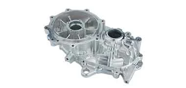 5-Axis Aluminum CNC Machining Parts
 5-Axis CNC Machining Aerospace Components