In the world of manufacturing and engineering, small details like edge treatments can make a big difference in the functionality, safety, and aesthetics of a part. A chamfer is one such feature—a simple angled cut that transforms sharp edges into sloped transitions. Commonly used in CNC machining, woodworking, and metalworking, chamfers help prevent injuries, ease assembly, and even prepare surfaces for welding or painting. Think of them as the unsung heroes in everyday products, from smartphone cases to automotive components.
This article dives into everything you need to know about chamfers, from their basic definition to advanced applications. Whether you’re a designer, engineer, or hobbyist, understanding chamfers can optimize your projects for better performance and cost-efficiency. We’ll explore types, comparisons with similar features like fillets and bevels, creation methods in CNC, and real-world case studies. By the end, you’ll have practical tips to incorporate chamfers effectively into your designs.
What Is a Chamfer?
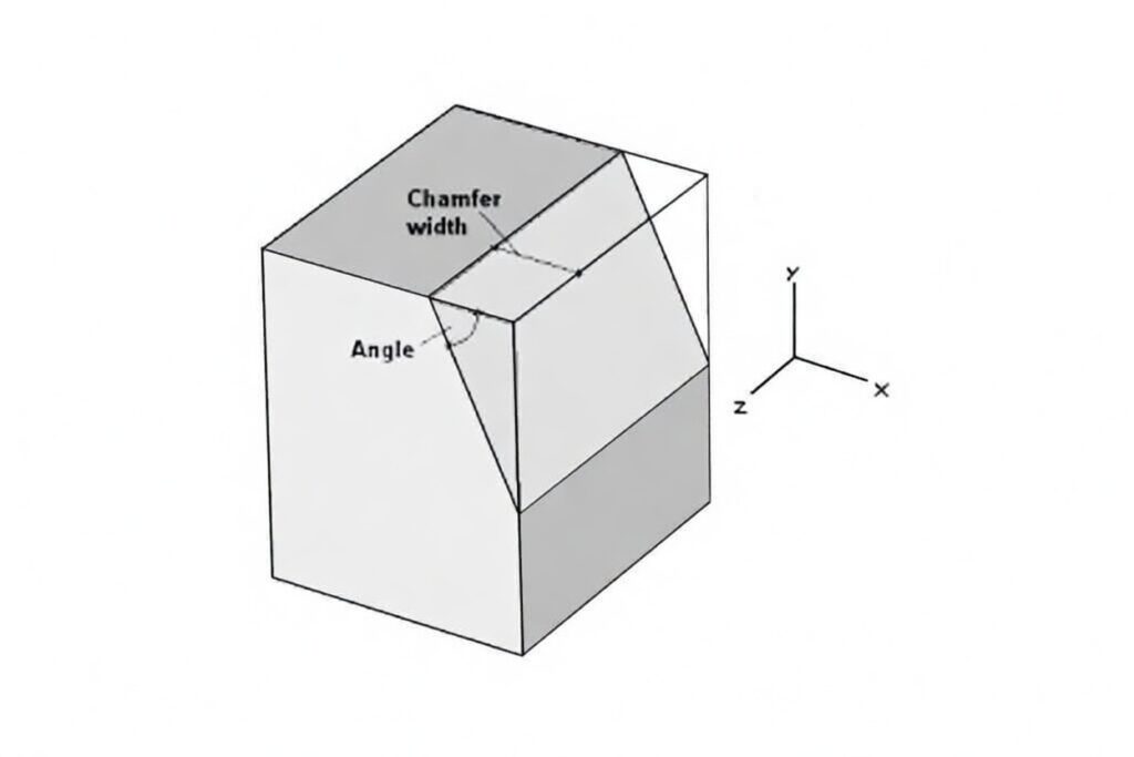
A chamfer is a transitional edge created by cutting away a sharp corner where two surfaces meet, typically at a 45-degree angle, though other angles are possible. This results in a flat, sloped surface that replaces the original 90-degree edge. In manufacturing, chamfers are essential for deburring—removing rough edges left from cutting processes—and improving part handling.
The term “chamfer” comes from the French word “chamfrein,” meaning “beveled edge,” and it’s been a staple in engineering since ancient times, seen in tools and architecture. Today, in modern machining, chamfers are specified in drawings with notations like “C1” for a 1mm chamfer at 45 degrees. They differ from rounded edges (fillets) by being straight and angled, making them quicker to produce.
Chamfers enhance durability by reducing stress concentrations slightly, though not as effectively as curves. They’re versatile across materials like metals, plastics, and wood and are often applied using specialized tools like chamfer mills in CNC setups. Fun fact: Even in 3D printing, chamfers are added to models to avoid sharp edges that could warp or fail during printing.
Types of Chamfers
Chamfers come in various forms, depending on the angle, symmetry, and application. Here’s a breakdown of the most common types:
- Standard 45-Degree Chamfer: The go-to option in manufacturing, cut at a 45-degree angle for balanced edge breaking. It’s ideal for general safety and assembly, as it provides a uniform slope without removing too much material. Commonly used in automotive parts and electronics housings.
- 60-Degree Chamfer: Often specified for screw holes or lead-ins, this steeper angle allows fasteners to sit flush or guides components into place. It’s popular in aerospace for its precision in mating surfaces, reducing the risk of misalignment.
- Asymmetric Chamfer: Where the cut is uneven on adjoining surfaces, such as different lengths on each side. This is useful in custom designs, like furniture edges, where aesthetics or functional clearance is key.
- Rounded Chamfer: A hybrid that softens the flat chamfer with a slight curve at the ends, blending into a fillet-like appearance. It’s less common but used in high-end consumer products for a smoother feel, though it requires more machining time.
Each type is chosen based on the part’s requirements, with 45-degree being the easiest to machine. In CNC, tools like V-groove bits or chamfer end mills handle these variations efficiently.
Chamfer vs. Fillet vs. Bevel
Chamfers, fillets, and bevels are all edge treatments, but they serve different purposes. Understanding their differences helps in selecting the right one for your design.
- Chamfer: A flat, angled cut (usually 45 degrees) that breaks sharp edges. It’s straight and quick to machine, ideal for safety and assembly.
- Fillet: A rounded curve with a specified radius, used to reduce stress concentrations by distributing loads evenly. It’s smoother but more expensive to produce in CNC due to the need for ball-end mills.
- Bevel: Similar to a chamfer but spans the full thickness of the material, creating a sloped edge between parallel surfaces. Bevels are often for welding prep or aesthetic joins, like in woodworking.
Here’s a quick comparison table:
| Feature | Chamfer | Fillet | Bevel |
|---|---|---|---|
| Shape | Flat, angled | Rounded, curved | Sloped, full-thickness |
| Common Angle | 45° | Radius-based (e.g., 2mm) | Variable, often 45° |
| Purpose | Safety, assembly ease | Stress reduction | Welding, large joins |
| Machining | Easy, low cost | More complex, higher cost | Moderate, material-heavy |
| Stress Relief | Moderate | High | Low |
Choose chamfers for cost-effective edge breaking, fillets for durability in load-bearing parts, and bevels for structural preparations.
Benefits of Chamfers
Chamfers offer several key advantages in manufacturing:
- Improved Safety: By eliminating sharp edges, chamfers reduce the risk of cuts during handling, assembly, or use—essential in consumer products like tools and gadgets.
- Easier Assembly: The angled edge acts as a lead-in, guiding parts together without snags, which speeds up production lines in industries like automotive.
- Aesthetic Enhancement: Chamfers give a clean, professional look, often used in furniture and electronics for a refined finish.
- Cost Savings: They’re simpler and faster to machine than curves, minimizing tool wear and production time.
- Durability Boost: While not as effective as fillets, chamfers slightly distribute stress, preventing cracks in brittle materials.
Overall, chamfers strike a balance between functionality and efficiency.
How to Create Chamfers in CNC
Creating chamfers in CNC machining is straightforward and involves these steps:
- Design the Part: Use CAD software like SolidWorks to specify chamfer dimensions (e.g., 1mm x 45°). Ensure the feature is added to edges or holes.
- Select Tools: Choose a chamfer mill, V-groove cutter, or standard end mill. For precision, opt for carbide tools with coatings to handle metals.
- Program the CNC: In CAM software (e.g., Fusion 360), set paths for the tool to follow the edge. Parameters include spindle speed (2000-5000 RPM for aluminum), feed rate (100-300 mm/min), and depth of cut.
- Machine the Chamfer: Run the cycle—the tool angles into the edge, removing material in one or multiple passes. For holes, use spot drills or countersinks.
- Post-Processing: Inspect for burrs and deburr if needed. Finishes like anodizing can enhance the chamfered surface.
Tips: Use coolant for heat dissipation, and test on scrap material first. This process typically adds minimal time to machining cycles.
Design Considerations
When incorporating chamfers, keep these factors in mind:
- Angle Selection: 45° is standard for versatility, but use 60° for fastener lead-ins or 30° for minimal material removal.
- Size and Depth: Specify chamfer width (e.g., 0.5-2 mm) based on part size—too large wastes material; too small may not deburr effectively.
- Material Impact: Softer materials like plastics allow deeper chamfers without cracking; harder metals require precise tooling to avoid chipping.
- Tolerances: Maintain ±0.1mm for precision fits, especially in assemblies.
- Cost and Manufacturability: Chamfers are low-cost but avoid over-specifying on non-critical edges to keep machining simple.
- Integration with Other Features: Ensure chamfers don’t interfere with threads or mating surfaces.
Balancing these ensures chamfers add value without complicating production.
Applications and Case Studies
Chamfers are ubiquitous across industries:
- Automotive: Used on engine blocks and gears for easy assembly and reduced wear.
- Aerospace: In turbine blades and fittings for stress relief and weight optimization.
- Electronics: On circuit board enclosures to prevent cable snags and improve ergonomics.
- Furniture: For table edges to enhance safety and aesthetics.
Case Study: In Boeing’s aircraft assembly, chamfers on aluminum panels reduced assembly time by 15% by easing fastener insertion, minimizing damage during high-volume production.
Another example: Apple’s iPhone chassis uses precise chamfers for a premium feel, combining functionality with design appeal in mass manufacturing.
Advantages and Limitations
Advantages:
- Quick and inexpensive to machine, reducing overall production costs.
- Enhances safety by removing sharp edges.
- Facilitates assembly and improves part mating.
- Versatile across materials and industries.
Limitations:
- Provides less stress relief than fillets, potentially leading to failures in high-load applications.
- Can remove too much material if oversized, weakening thin parts.
- Requires precise tooling for consistency in complex geometries.
- Not ideal for aesthetic curves where fillets shine.
Chamfers excel in practical, cost-sensitive scenarios but may need supplementation in demanding designs.
Best Practices and Tips
- Standardize Angles: Stick to 45° for most applications to simplify tooling and reduce errors.
- Use Software Aids: Leverage CAD auto-chamfer tools for quick design iterations.
- Test Prototypes: Machine samples to verify fit and finish before full runs.
- Combine with Fillets: Use chamfers on external edges and fillets internally for optimal performance.
- Avoid Overuse: Only apply where needed to minimize machining time.
- Maintenance: Regularly sharpen tools to prevent rough chamfers.
Following these ensures efficient, high-quality results.
FAQ
What is the difference between a chamfer and a bevel?
A chamfer is a small angled cut at a corner, while a bevel spans the full edge between parallel surfaces, often for larger joins like welding.
When should I use a chamfer instead of a fillet?
Use chamfers for cost-effective safety and assembly; opt for fillets when maximum stress reduction is needed.
Can chamfers be added post-machining?
Yes, using hand tools or secondary operations, but it’s more efficient to include them in the initial CNC program.
What angle is best for chamfers?
45 degrees is standard for balance, but adjust based on function—60° for lead-ins, 30° for subtle edges.
Are chamfers necessary in 3D printing?
They’re helpful to avoid sharp edges that could cause print failures or post-processing issues.
What is a chamfer in CNC machining?
An angled cut replacing sharp corners for safety and assembly. It improves manufacturability by easing tool access and reducing burrs.
Why use 45° chamfers?
They’re standard, easy to machine, and balanced for most applications, providing adequate stress relief without complexity.
How does chamfer differ from fillet?
Chamfer is flat and angled for assembly; a fillet is rounded for superior stress distribution in load-bearing areas.
What tools create chamfers?
Chamfer mills, end mills, or countersinks; select based on angle and material for optimal results.
Can chamfers reduce costs?
Yes, by simplifying assembly, minimizing rework, and extending tool life through efficient designs.
What are common mistakes?
Oversizing, inconsistent specs, and ignoring access can be avoided by standardizing and early CAD integration.
How to specify chamfers on drawings?
Use “CxA°” with tolerances; include symbols for clarity to prevent misinterpretation.
Are chamfers necessary for all parts?
Not always, but recommended for edges in high-use applications to enhance safety and durability.
What materials suit chamfering?
Metals, plastics; adjust parameters for hardness—e.g., coolant for metals, low speeds for plastics.
Future of chamfering?
AI optimization, automation, and sustainability are trends toward hybrid manufacturing for complex edges.
Conclusion
Chamfers are a fundamental yet powerful feature in manufacturing, offering simplicity, safety, and efficiency. From basic edge breaking to advanced applications in aerospace and electronics, they enhance parts without adding complexity. By understanding their types, benefits, and best practices, you can integrate chamfers to optimize designs and cut costs. Ready to chamfer your next project? Start with a prototype and see the difference.