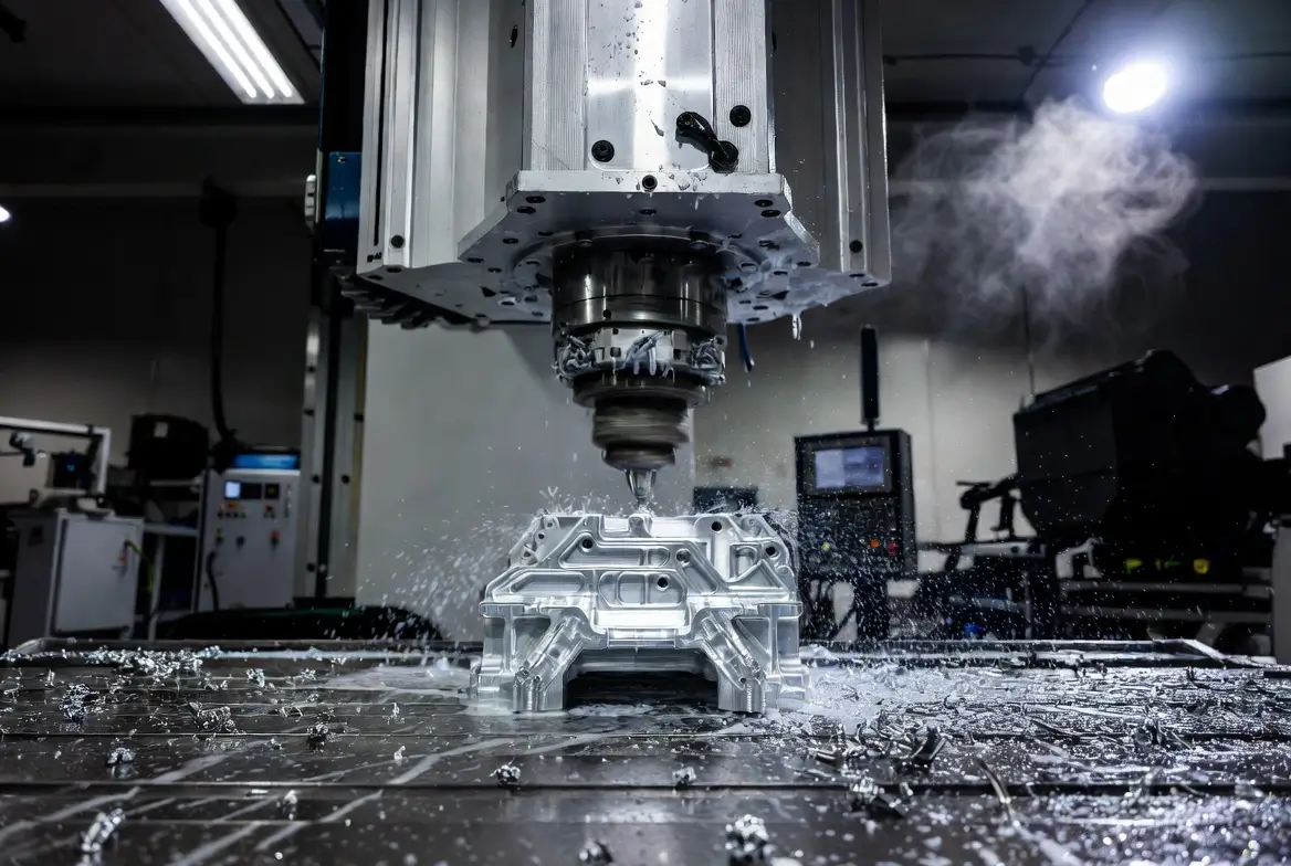
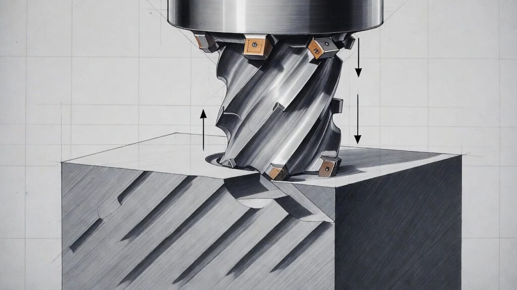
Face milling is a key machining operation used to create flat, precise surfaces on workpieces. It utilizes a rotating cutter with its axis perpendicular to the surface, where the primary cutting action occurs on the tool’s face (via inserts or teeth). This method delivers high material removal rates and superior surface finishes, making it essential in CNC milling centers and conventional mills.
This comprehensive guide covers face milling fundamentals, including its definition, step-by-step process, tool selection, operation types, applications, advantages, disadvantages, and comparisons to related processes. It reflects 2025–2026 advancements like high-feed milling, AI-optimized paths, wiper insert improvements, and sustainable machining trends
What Is Face Milling?
Face milling removes material from the top face of a workpiece using a cutter oriented perpendicular to the surface. The tool’s face-mounted cutting elements shear away material, producing flat, parallel planes efficiently.
What Is Face Milling Used For?
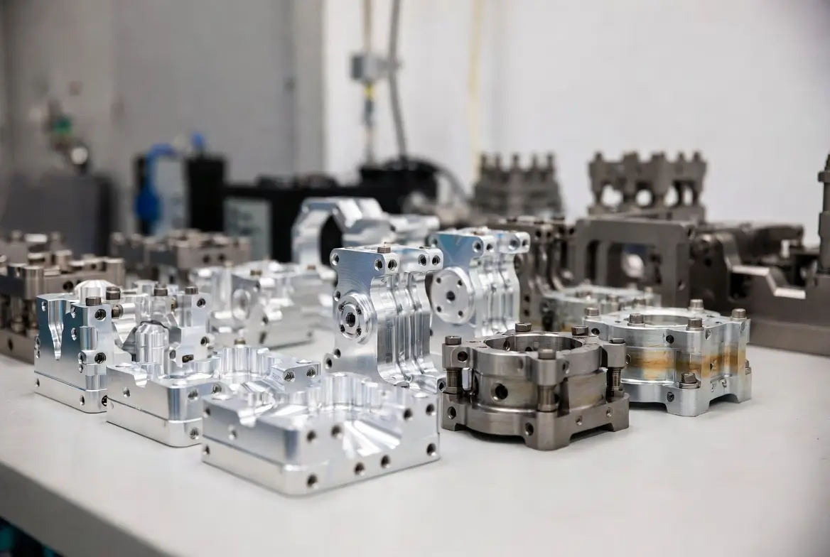
Face milling creates reference flat surfaces, prepares stock for further operations, and achieves fine finishes on large areas. It is commonly applied to engine blocks, mold bases, machine beds, housings, plates, and structural components where parallelism and surface quality are critical.
What Is Face Milling Also Called?
It is occasionally called surfacing or slab milling (especially with large tools), though “face milling” is the standard term. When using shell mills, it may informally be referred to as shell milling.
What Are the Features of a Face Milling Cutter?
A typical face milling cutter includes:
- Arbor or shank for machine mounting
- Cutting head/body with multiple insert pockets
- Indexable inserts (carbide, ceramic, CBN, PCD)
- Keys or drive mechanisms to prevent slippage
- Retaining bolt or drawbar connection
- Optional through-tool coolant channels
- Lead/approach angles (10–90°) and wiper edges for finish enhancement
Inserts are interchangeable for different materials, geometries, and coatings.
How Does Face Milling Differ From the Other Types of Milling?
- Peripheral milling: Cutting occurs on the tool’s circumference/sides; ideal for slots, profiles, and heavy stock removal but less efficient for broad flats.
- End milling: Smaller tools for contours, pockets, 3D features, and detailed work; not optimal for large-area surfacing.
- Chamfer, profile, shoulder milling: Targeted at specific edge breaks, contours, or steps.
- Face milling: Specialized for wide, flat surfaces with superior speed and finish.
How Does the Face Milling Process Work?
The process follows these main steps:
1. Arrange the Workpiece
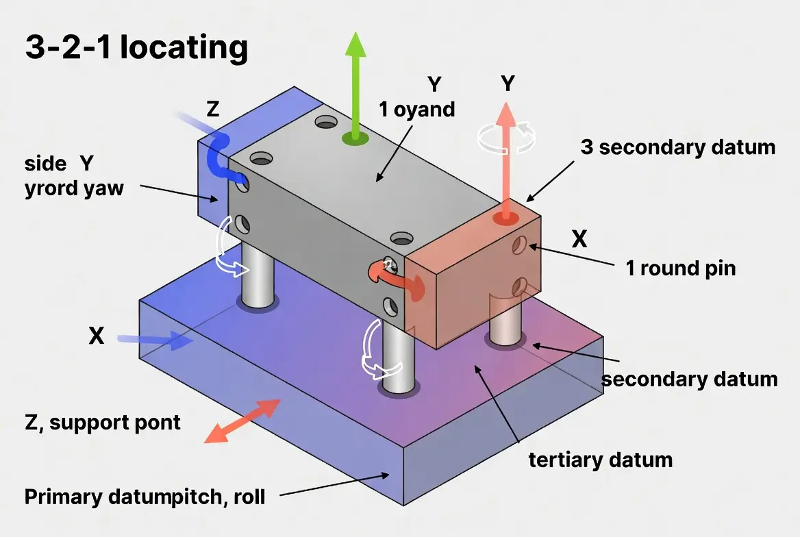
Secure the workpiece firmly using a vise, clamps, fixture, or magnetic chuck. Use parallels or shims to level it and ensure the surface is perpendicular to the spindle. Proper clamping prevents vibration and ensures uniform tool engagement.
2. Place the Milling Machine
Position the spindle axis perpendicular to the workpiece face. Adjust the Z-height for the desired depth of cut. On CNC machines, use probing/edge finding for accuracy.
3. Set the Feed Rate and Spindle Speed
Determine parameters based on material, tool, rigidity, and goals:
- Cutting speed (Vc): Varies by tool/material (see table below)
- Feed per tooth (fz): 0.05–0.4 mm/tooth typical
- Depth of cut (ap): 0.5–5 mm roughing; 0.1–0.5 mm finishing
- Width of cut (ae): 60–90% of cutter diameter
High-feed milling (shallow ap, high fz) achieves 3–5× higher productivity in modern setups.
4. Perform Machining
Run the cut, preferably climb milling on CNC for better finish and tool life. Use adaptive CAM toolpaths to minimize forces and optimize chip load.
How Long Does the Process of Face Milling Take?
Machining time is calculated as:
Tc = L / vf
(Tc = time in minutes, L = cut length in mm, vf = feed rate in mm/min)
Example: 800 mm cut at 1200 mm/min → Tc ≈ 0.67 min (40 seconds), excluding rapids, tool changes, and positioning.
What Is the Cutting Speed of Face Milling?
Approximate cutting speeds (m/min, 2026 guidelines):
| Cutting Tool Material | Mild Steel | Stainless Steel | Aluminum | Titanium | Notes (2026 trends) |
|---|---|---|---|---|---|
| High-Speed Steel | 20–50 | 10–30 | 50–120 | 10–25 | Prototypes, soft materials |
| Cemented Carbide (coated) | 100–250 | 60–180 | 300–800 | 40–120 | Production standard; coatings key |
| Ceramics | 400–800 | 200–600 | — | 100–400 | High-speed hard materials |
| Cubic Boron Nitride (CBN) | 300–700 | 150–500 | — | — | Hardened steels |
| Polycrystalline Diamond (PCD) | — | — | 800–2000 | — | Non-ferrous, composites |
When To Use Face Milling?
Use face milling for large flat surfaces requiring good finish and moderate-to-high material removal, especially when establishing datums or preparing for secondary operations.
What Are the Materials That Can Be Used for Face Milling?
Virtually all machinable materials: aluminum alloys, steels (mild to hardened), stainless, titanium, cast iron, nickel alloys, plastics, and composites.
How Does the Choice of Materials Affect Face Milling Effectiveness?
Softer materials (e.g., aluminum) permit higher speeds/feeds and mirror finishes. Harder/tougher alloys demand robust tools, lower parameters, advanced coatings, and coolant to control heat, built-up edge, and tool wear.
How To Choose the Right Face Milling Tools?
Consider:
- Material/Grade: Match to workpiece (carbide versatile; ceramics/CBN for hard; PCD for non-ferrous)
- Diameter: Larger for fewer passes (ideally > workpiece width)
- Coating: TiAlN, AlCrN, and nanolayers for heat/friction reduction
- Lead Angle: 45° balanced; 10–15° high-feed; 75–90° heavy roughing
- Number of Teeth/Flutes: More for higher feeds; balance chip evacuation
- Wiper Inserts: Essential for fine Ra at production speeds
- Machine Power/Rigidity/Coolant: Ensure compatibility
What Are the Right Tools for Face Milling?
1. End Mills
Smaller diameters are for light facing, contours, or when multi-axis work is needed; limited for broad surfacing.
2. Shell Mills
Most popular; large indexable bodies with replaceable inserts; efficient, cost-effective for production flats.
3. Fly Cutters
Single-insert tools produce ultra-fine finishes on soft materials with minimal power.
Specialized high-feed face mills (low-angle geometry) excel in modern high-productivity shops.
What Are the Different Types of Face Milling Operations?
1. General Face Milling
Standard 45° approach; versatile across materials and setups.
2. Heavy-Duty Face Milling
High DOC/material removal; robust tools for castings/forgings.
3. High Feed Milling
Shallow DOC + aggressive feed; dominant for speed gains.
4. Finishing With Wiper Inserts
Light passes with wiper geometry and achieves Ra 0.2–0.4 µm at high feeds.
What Are the Applications of Face Milling?
- Creating/leveling flat datums on raw stock
- Machining engine/transmission housings and mold bases
- Preparing large plates and structural elements
- Finishing gasket/sealing surfaces in automotive/aerospace
- Squaring blocks before pocketing/drilling
What Are the Advantages of Face Milling?
- High material removal rates (especially high-feed)
- Excellent surface finishes (Ra < 0.8 µm routine)
- Efficient large-area coverage in fewer passes
- Reduced post-processing needs
- Versatile across materials
- Indexable tools minimize costs over time
- Lower forces in optimized geometries
- Compatible with CNC automation/AI paths
What Are the Disadvantages of Face Milling?
- Demands rigid setups to avoid chatter
- Higher initial cost for large indexable cutters
- Chip management issues in gummy materials
- Limited for small/intricate features or deep internals
- Potential exit burrs if parameters suboptimal
Is Face Milling Considered Expensive?
Initial tooling can be higher for large cutters, but it’s highly cost-effective at scale due to speed, insert longevity, and reduced cycle times.
Can You Bore With a Face Mill?
Limited—suitable for light spot facing or shallow counterboring, but dedicated boring tools offer better rigidity and precision for accurate holes.
What Is the Difference Between Face Milling and Peripheral Milling?
Face milling cuts with the tool face for flats; peripheral uses sides for slots/profiles and deeper removal.
What Is the Difference Between Face Milling and Shell Milling?
Shell milling refers specifically to using shell mill tools for face milling operations.
What Is the Difference Between Face Milling and End Milling?
End milling suits detailed 3D work with smaller tools; face milling prioritizes broad flats with larger cutters for efficiency/finish.
Summary
Face milling is a cornerstone process for producing precise flat surfaces quickly and reliably. With ongoing advancements in tooling (high-feed, wipers), CAM optimization, and sustainable techniques (MQL, sensor monitoring), it delivers unmatched productivity in 2026 manufacturing environments. Mastering parameters, tool selection, and setup ensures optimal results across diverse applications.