Last month, a long-term aerospace client in Germany sent back an entire shipment of 320 titanium brackets after their incoming inspection revealed that three critical holes were out of position by just 0.007 mm. The parts looked perfect to the naked eye, but the GD&T callout on the drawing was unforgiving. That single batch rejection cost us $68,000 in rework, air freight, and lost trust — and it happened because our final quality check had missed a subtle fixture deflection during CMM verification.
Moments like this are why I’ve spent the last 12 years as the founder of a CNC machining service in China obsessing over quality testing systems. Every day, our team inspects parts for clients who demand zero defects in medical implants, aircraft components, oil & gas valves, and high-speed automation equipment.
In this complete 2026 guide, I share the exact quality testing methods, standards, equipment choices, GD&T application techniques, statistical process control strategies, digital quality management tools, and prevention strategies that have helped us reduce rejection rates from 4.8% to under 0.4% over the past three years. Whether you run a CNC shop, manage quality for an OEM, or are responsible for supplier development, these practical insights will help you catch problems before they leave your door and build lasting customer confidence.
CNC Parts Quality Testing: Importance and Challenges
Quality testing is the final gatekeeper that protects your reputation, profitability, and customer relationships. A single undetected defect can trigger warranty claims, safety recalls, or loss of certification. In 2026, with tighter tolerances, complex geometries, and stricter regulatory requirements (AS9100, ISO 13485, IATF 16949), effective quality testing has become a true competitive advantage.
The main challenges include:
- Achieving consistent ±0.005 mm or tighter tolerances on complex 5-axis parts
- Measuring surface roughness to Ra 0.2–0.8 μm reliably across different materials
- Verifying material properties and microstructure without destroying the part
- Performing first-article inspection (FAI) quickly without delaying production
- Maintaining full digital traceability for customer audits and regulatory compliance
Shops that master these challenges see rejection rates drop from 5–8% to under 0.5%, significantly improving profitability and customer trust. According to industry reports, the cost of poor quality in CNC machining can reach 15–25% of total revenue if not properly controlled.
Main Quality Testing Methods Comparison
Here is a practical comparison of the most important testing methods used in CNC machining:
| Method | Purpose | Equipment | Typical Tolerance/Accuracy | Cost Level | Best For | Frequency |
|---|---|---|---|---|---|---|
| Dimensional Inspection | Size and geometry | CMM, calipers, micrometers | ±0.002 mm | Medium | Critical features | 100% |
| GD&T Inspection | Form, position, orientation | CMM with GD&T software | ±0.005 mm | High | Aerospace, medical | 100% |
| Surface Roughness | Ra, Rz, Rq values | Profilometer, optical scanner | Ra 0.2–3.2 μm | Medium | Sealing surfaces, medical parts | 100% |
| Hardness Testing | Material strength | Rockwell, Brinell, Vickers | ±1–2 HRB/HRC | Low | Heat-treated parts | Sampling |
| Material Verification | Chemistry & microstructure | PMI spectrometer, microscope | Full composition | High | High-alloy parts | Sampling |
| Non-Destructive Testing | Internal defects | Ultrasonic, dye penetrant | Detect cracks >0.1 mm | Medium | Safety-critical parts | Sampling |
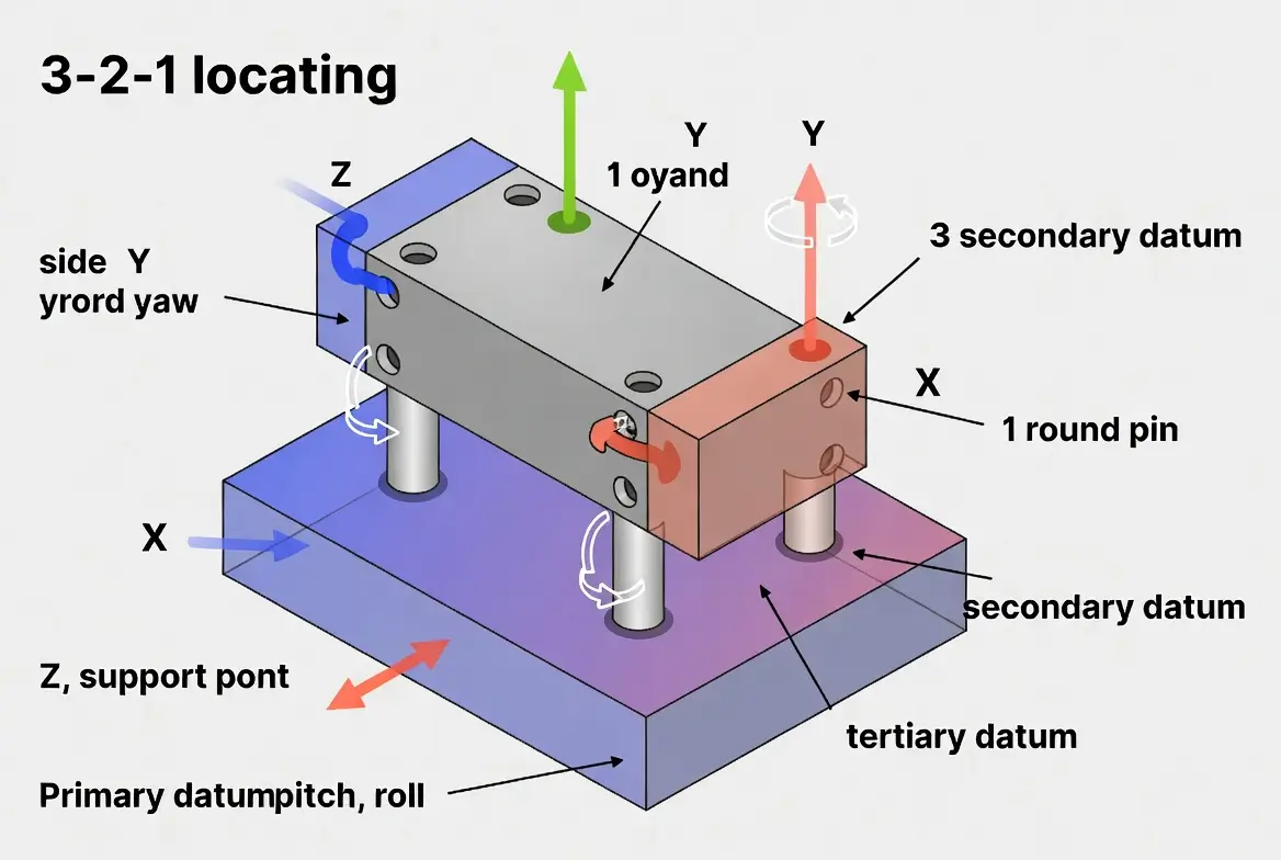
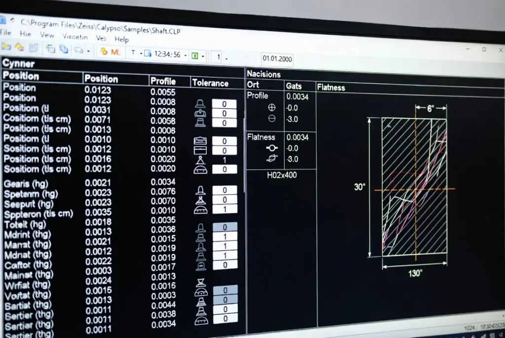
Dimensional & Geometric Tolerancing Inspection (GD&T)
GD&T is the universal language of precision. According to ASME Y14.5-2018, proper GD&T ensures parts assemble correctly even with manufacturing variation.
Key steps in our shop:
- Define primary, secondary, and tertiary datums on the drawing
- Apply position, profile, flatness, parallelism, and perpendicularity tolerances
- Use CMM with GD&T software for automated reporting
- Verify bonus tolerance when features are at maximum material condition (MMC)
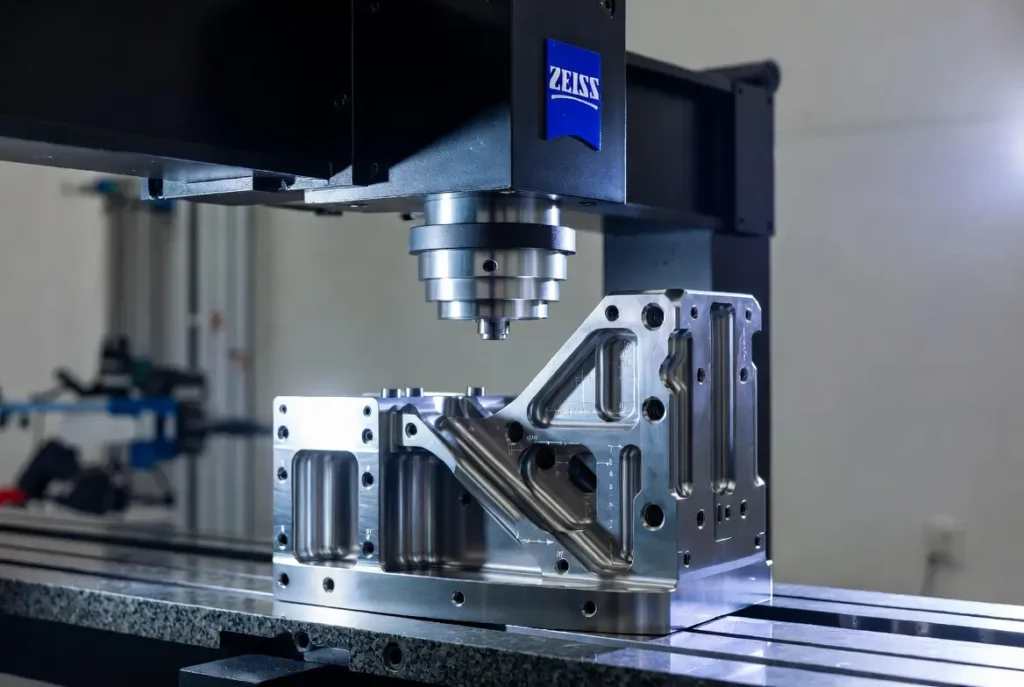
We use Zeiss or Hexagon CMMs with Calypso or PC-DMIS software to generate detailed reports that customers accept without question. This approach has reduced interpretation errors by over 70% compared to traditional dimensioning.
Surface Roughness & Appearance Inspection
Surface finish directly affects sealing performance, friction, fatigue life, and appearance. ISO 4287 and ISO 4288 define parameters such as Ra, Rz, and Rq.
We measure every critical surface using Mitutoyo SJ-410 or Taylor Hobson profilometers. For medical and aerospace parts, we also use optical 3D scanners to map the entire surface in minutes, catching defects that traditional stylus methods might miss. Typical acceptance criteria: Ra 0.4 μm for sealing surfaces and Ra 1.6 μm for general machined faces.
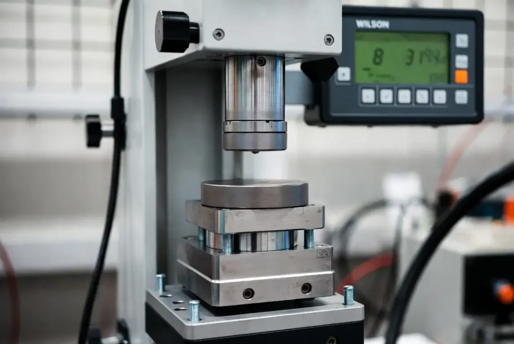
Material Property Testing
Hardness, tensile strength, and microstructure must be verified. ASTM E18 covers Rockwell hardness testing. We perform in-house hardness checks on every batch and send samples for third-party metallographic analysis when required by the customer. For high-alloy parts, we use portable XRF spectrometers for positive material identification (PMI) to ensure the correct grade.
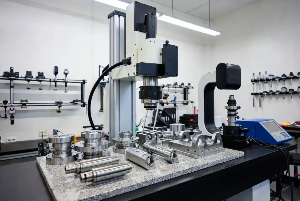
CNC Machining Quality Control Key Parameters & Equipment Recommendations
Recommended equipment in a modern CNC shop:
- CMM (Zeiss, Hexagon, Mitutoyo) for dimensional and GD&T
- Surface roughness tester (Mitutoyo SJ-410 or equivalent)
- Hardness tester (Wilson Rockwell or portable Brinell)
- PMI spectrometer for alloy verification
- Digital height gauge and micrometers for in-process checks
- Optical 3D scanner for complex geometries
DFM Design & Quality Prevention
The best quality control starts at the design stage. Our DFM checklist includes:
- Avoid sharp internal corners (minimum 0.5 mm radius)
- Specify realistic tolerances only where functional
- Add inspection datums and tooling holes
- Design for easy fixturing and probing access
- Consider material machinability during material selection
Real Industry Cases & ROI Analysis
- Aerospace bracket project: Full GD&T implementation reduced rejection rate from 12% to 0.3%, saving $85,000 per year.
- Medical implant components: Surface roughness control extended product life by 40% and helped pass ISO 13485 audit on the first attempt.
Quality Control Standards
All parts are inspected per ISO 2768, ASME Y14.5, and customer-specific requirements.
FAQs
What are the main quality tests for CNC machined parts?
Dimensional, GD&T, surface roughness, hardness, and material verification.
How to check surface finish?
Use a profilometer to measure Ra and Rz values.
What standards apply?
ASME Y14.5 for GD&T, ISO 2768 for tolerances, ASTM E18 for hardness.
Conclusion
Quality testing is the final gatekeeper that protects your reputation and profitability. By implementing systematic methods, using the right equipment, and applying GD&T correctly, you can achieve zero-defect delivery and win more high-value customers.
As a Chinese CNC machining supplier, we help global clients build robust quality systems daily.
Ready to improve your CNC part quality? Contact us today for a free quality audit and DFM review. Let’s turn your parts into reliable, customer-approved components.
References
[1] ASME Y14.5-2018 — Dimensioning and Tolerancing. https://www.asme.org/codes-standards/find-codes-standards/y14-5-geometric-dimensioning-tolerancing
[2] ISO 2768 — General Tolerances for Machined Parts. https://www.iso.org/standard/38007.html
[3] ISO 4287 — Geometrical Product Specifications — Surface Texture. https://www.iso.org/standard/4287.html
[4] ASTM E18 — Standard Test Methods for Rockwell Hardness. https://www.astm.org/e0018-20.html