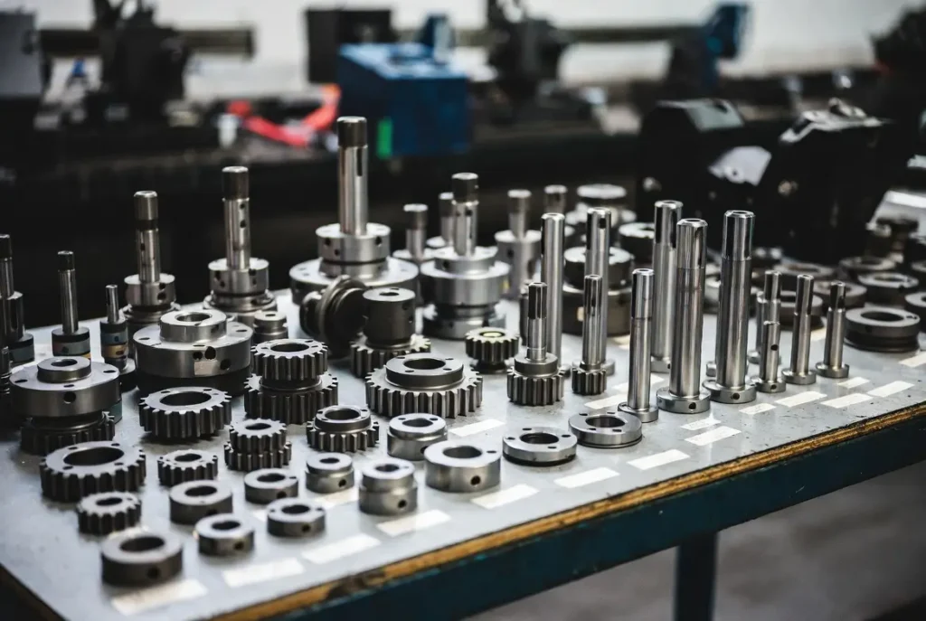
CNC milling parts are the critical components that power modern precision manufacturing. From the heavy-duty machine bed and high-speed spindle to ball screws, linear guides, automatic tool changers, and coolant systems — every CNC milling part directly controls your ±0.001 mm accuracy, surface finish, and production speed.
A single worn spindle bearing or contaminated guide can cost thousands in scrap and downtime, while the right CNC milling parts can cut cycle times by up to 80% and deliver 24/7 repeatable precision.
The global CNC milling market is booming — projected to reach US$120.82 billion by 2035 at a 3.60% CAGR — driven by EVs, semiconductors, and Industry 4.0. In this guide you’ll discover:
- Complete breakdown of all CNC milling parts with names, functions, materials, and performance impact
- Labeled diagrams and free CNC milling parts PDF checklist
- Step-by-step “how they work together” flowchart
- Spare parts buying guide + maintenance checklist
- Real-world applications for aluminum milling and small parts
- 2025–2035 trends (AI predictive maintenance, hybrid systems, etc.)
Whether you’re a shop owner, programmer, technician, or buyer, this guide equips you to select, maintain, and upgrade with confidence.
Yet the real magic — and biggest risk — lies in the parts themselves. Understanding every component, from the vibration-damping bed to the AI-ready controller, is what separates consistent lights-out production from costly surprises.
What Is a CNC Milling Machine?
A CNC (Computer Numerical Control) milling machine is a subtractive manufacturing powerhouse that uses rotating multi-point cutting tools to remove material from a stationary or rotating workpiece according to digital instructions. Unlike manual mills that rely on operator skill and handwheels, every axis movement, spindle speed, feed rate, tool change, and coolant flow is governed by pre-programmed G-code and M-code, ensuring repeatability that human hands simply cannot match.
Working Principles
The core principle is elegant yet computationally intensive: a computer translates a 3D CAD model into precise tool paths through CAM software. The machine then executes those paths across multiple axes while the spindle rotates at speeds ranging from 6,000 RPM for steel to 40,000+ RPM for aluminum and composites. Key physical parameters include:
- Feed rate (inches or millimeters per minute – how fast the tool advances)
- Spindle speed (surface feet per minute or RPM)
- Depth of cut and stepover (radial and axial engagement percentages)
- Chip load per tooth (critical for tool life)
Modern closed-loop systems use high-resolution encoders, glass linear scales, and real-time feedback to correct positioning errors within microseconds, achieving repeatability better than 0.002 mm even under thermal expansion or heavy cutting loads.[1] Advanced controllers now incorporate adaptive feed-forward algorithms that automatically slow down in corners or increase speed in straight lines to maintain constant chip load.
Pro Tip: Always run a full CAM simulation—including collision detection and material removal verification—before hitting “Cycle Start.” A 30-second virtual dry run has prevented countless crashes that would otherwise cost thousands in tooling and machine damage.
Core Components
Every CNC mill is a precisely engineered symphony of 10 critical systems. Below is the fully expanded breakdown, now including technical specifications, material comparison tables, real-world failure case studies, selection checklists, upgrade ROI examples, and precise maintenance intervals based on 2025 industry best practices.
1. Machine Bed/Base
Function: The foundational element that supports the entire machine structure and provides critical vibration damping.
Sub-components: Ribbed casting, precision leveling feet, integrated chip evacuation channels, and sometimes polymer concrete fill for ultra-damping.
Materials: High-grade gray cast iron (superior damping ratio), Meehanite (enhanced stability), or polymer concrete in ultra-precision models (up to 10× better vibration absorption than steel).
Performance Impact: Poor bed rigidity directly causes chatter marks, dimensional drift, and degraded surface finish (Ra values jumping from 0.8 µm to 3.2 µm). A rigid bed maintains geometric accuracy even under 10,000 N cutting forces.
Material Comparison Table (text version):
- Gray Cast Iron: Excellent damping, moderate cost, standard on 80% of machines
- Meehanite: 20% better stability, used in high-end VMCs
- Polymer Concrete: Lowest vibration transmission, ideal for micro-milling but higher cost
Practical Tips & Checklist:
- Level the machine every 3 months to 0.02 mm/m using a precision spirit level.
- Never place heavy fixtures on edges—always use center T-slots.
- Clean chip troughs daily to prevent thermal distortion from chip accumulation.
- Install 6–8 isolation pads rated for machine weight on shop floors prone to vibration.
Real-World Failure Case: A Midwest job shop lost 14 hours of production when foundation settling caused 0.03 mm Z-drift on a $180k VMC. Solution: Re-leveling + isolation pads restored accuracy in under 2 hours.
Upgrade ROI: Switching to polymer-filled bed on older machines can reduce vibration by 40% and extend tool life 15–25%, paying for itself in 9–12 months through reduced scrap.
Maintenance Interval: Quarterly laser leveling; annual full foundation inspection.
2. Column
Function: Vertical support structure for the spindle head and Z-axis travel.
Sub-components: Box-way or linear guide mounting surfaces, counterweight or servo-assisted systems, internal ribbing, and sometimes thermal compensation sensors.
Materials: Stress-relieved cast iron or welded steel with finite element analysis-optimized rib patterns.
Performance Impact: Column deflection under heavy cuts (especially on tall workpieces) directly degrades Z-axis accuracy, causing tapered walls or out-of-square features. A well-designed column maintains <0.005 mm deflection at full extension.
Practical Tips:
- Demand ribbed internal designs in spec sheets—more ribs equal exponentially better torsional stiffness.
- Torque column-to-bed bolts to Grade 12.9 specs (typically 250–400 Nm).
- Annual laser alignment to detect twist or lean before it affects parts.
Expanded Insight: In 5-axis configurations, the column must also resist torque from tilting heads. Manufacturers now use finite element simulation during design to predict and eliminate resonance frequencies.
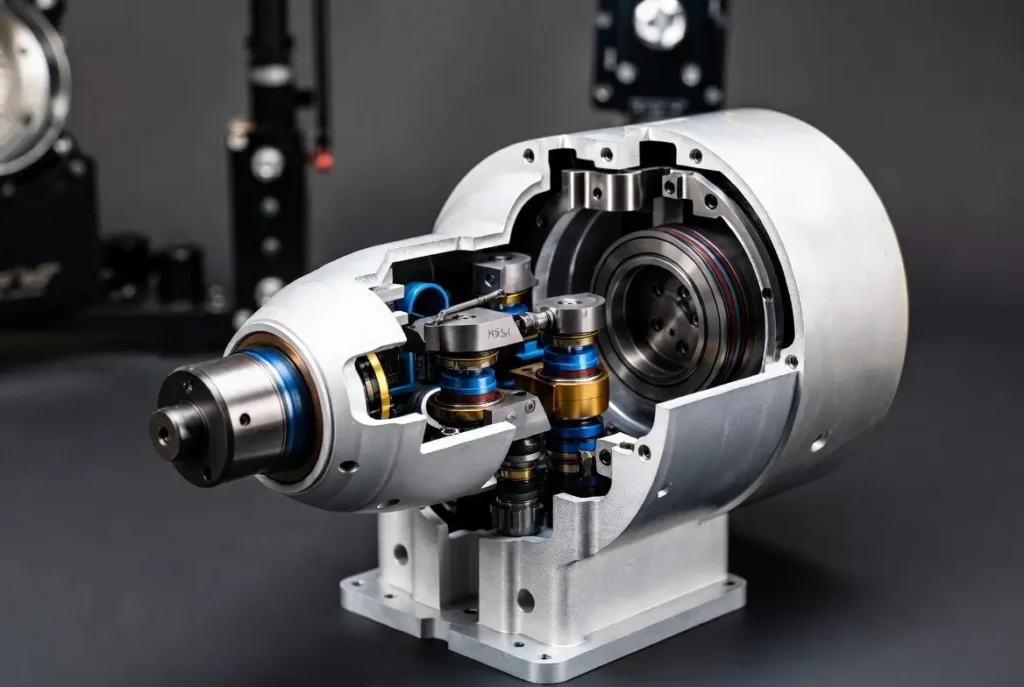
3. Spindle Assembly
Function: The high-speed rotating “heart” that drives the cutting tool.
Sub-components: Tool taper (BT40/CAT40/HSK63), hybrid ceramic or angular-contact bearings, hydraulic or pneumatic drawbar, integrated cooling jacket, speed encoder, and optional through-tool coolant channels.
Materials: High-alloy steel shaft, ceramic hybrid bearings (for 40,000+ RPM), liquid-cooled housings.
Performance Impact: Spindle runout exceeding 0.002 mm destroys tool life (cutting it in half) and surface finish. HSK tapers with 40,000 RPM models now dominate high-speed aluminum machining.[4]
Practical Tips:
- Mandatory 10–15 minute warm-up at 50% speed before production.
- Weekly laser or touch-probe runout verification (<0.001 mm ideal).
- Upgrade to air-oil mist for speeds >15,000 RPM; monitor bearing temperature with embedded sensors.
Failure Case: A medical implant manufacturer experienced catastrophic bearing failure after skipping warm-ups, leading to $18,000 in scrap and a 3-day shutdown. Post-upgrade with ceramic bearings and chiller, tool life increased 3×.
Upgrade ROI: Retrofitting a 24,000 RPM HSK spindle on a 10-year-old VMC typically pays back in 6–8 months via faster cycle times and 30% longer tool life.
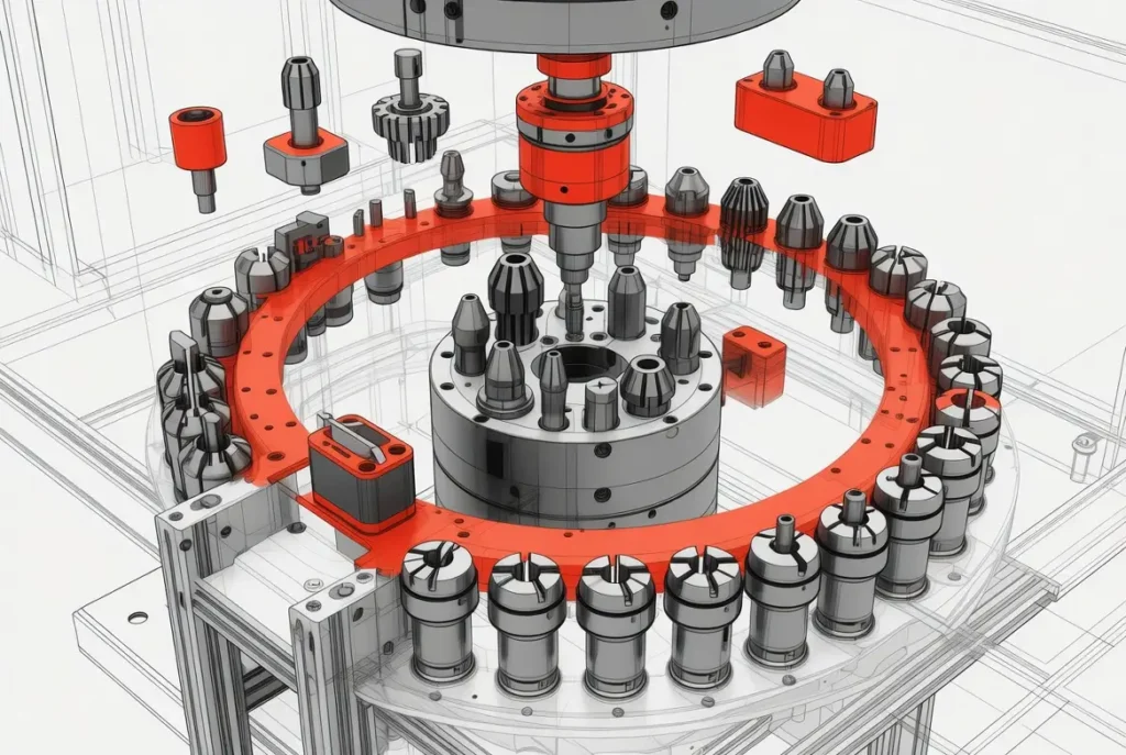
4. Automatic Tool Changer (ATC)
Function: Enables tool swaps in 1–3 seconds without operator intervention.
Sub-components: Drum, chain, or umbrella-style magazine (30–120 pockets), servo-driven gripper arm, proximity sensors, and tool pocket clamps.
Materials: Hardened steel pockets, lightweight aluminum/composite body.
Performance Impact: A single jam halts the entire job. Chain magazines excel with heavy tools in 5-axis work; umbrella types are faster for lighter tools.
Practical Tips:
- Compressed-air blow-off of tapers before every insertion.
- Enable tool-life management in the controller for automatic replacement.
- Lubricate gripper pivots every 1,000 cycles.
Selection Checklist: Choose 60+ pocket capacity if running more than 30 unique tools daily; verify max tool weight rating matches your heaviest end mills.
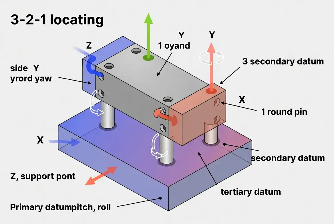
5. Worktable & Pallet System
Function: Securely holds and precisely positions the workpiece.
Sub-components: Precision T-slots or grid plates, ground surface, integrated 4th/5th-axis rotary tables, pallet changers with hydraulic clamping.
Materials: Cast iron or hardened steel ground to 0.005 mm flatness.
Performance Impact: Even 0.01 mm table deviation transfers directly to part parallelism errors in multi-setup runs.
Practical Tips: Torque clamps evenly; verify pallet repeatability with a dial indicator after every swap. Add modular zero-point fixturing for sub-60-second changeovers.
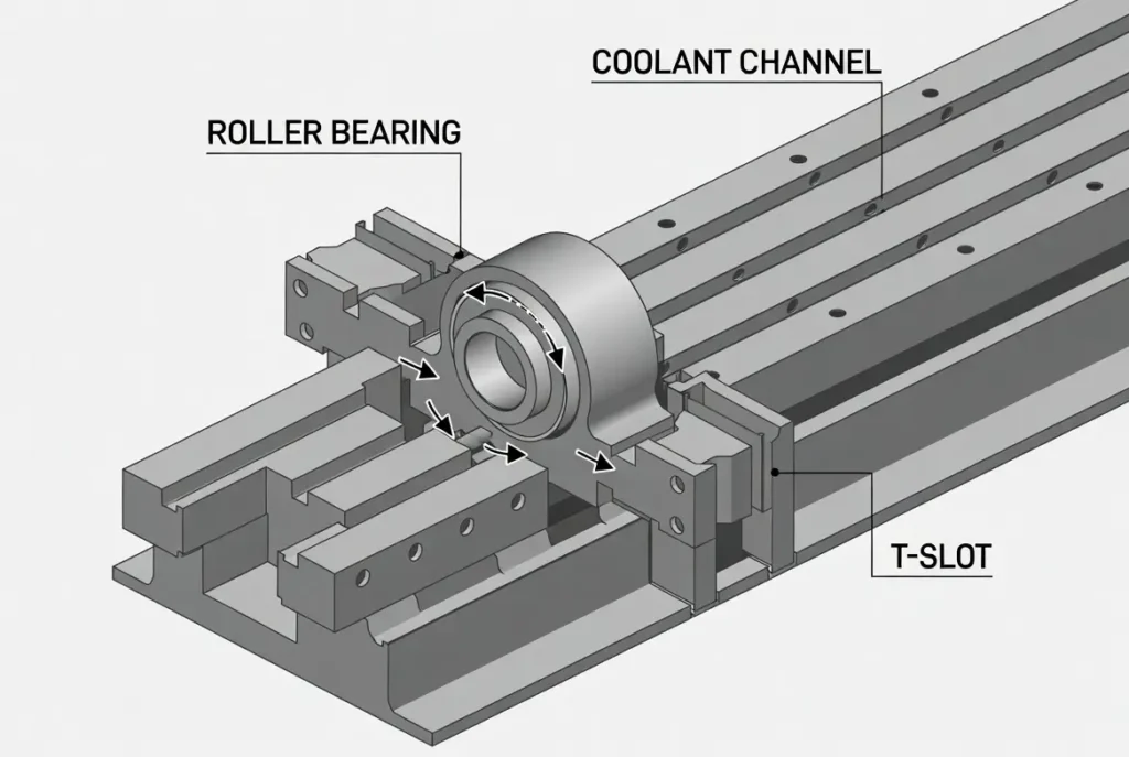
6. Linear Guides & Ways
Function: Deliver frictionless, high-precision axis travel.
Sub-components: Hardened rails, recirculating ball or roller blocks, seals, wipers, preload adjustment.
Materials: HRC 58–62 steel or roller guides for heavy loads.
Performance Impact: Worn guides introduce backlash and positioning errors up to 0.02 mm.[5]
Maintenance Tip: Daily wipe-down; re-grease every 500 hours. Replace wipers at first sign of damage to prevent contamination.
7. Ball Screws & Drive System
Function: Convert servo rotation into precise linear motion.
Sub-components: Ground or rolled screw shaft, preloaded nut, thrust bearings, end supports.
Materials: High-carbon alloy steel.
Performance Impact: Proper preload eliminates backlash for perfect contouring.[4]
Practical Tips: Listen for noise during rapids; replace every 8,000–12,000 hours or when error >0.01 mm. Use C3/C5 ground screws for sub-micron work.
8. CNC Controller & Electrical System
Function: The intelligent brain interpreting G-code and driving all axes.
Sub-components: Multi-core CPU, I/O modules, servo amplifiers, 15–21″ touchscreen HMI, Ethernet/OPC-UA connectivity.
Performance Impact: Fanuc, Siemens, and Heidenhain controllers now support 5-axis simultaneous motion plus AI path optimization, cutting cycle times 15–30%.
Practical Tips: Update firmware quarterly; install UPS and surge protection; enable remote diagnostics for instant troubleshooting.
9. Coolant System
Function: Temperature control and chip evacuation.
Sub-components: High-pressure pump (up to 1,000 psi), stainless tank, multi-nozzle array, paper/magnetic filtration.
Performance Impact: Proper coolant extends tool life 3–5× and eliminates thermal growth errors.
Pro Tip: Synthetic for aluminum (7–10% concentration checked weekly with refractometer); semi-synthetic for steels. Deep-clean tank every 3 months.
10. Lubrication & Chip Management System
Function: Automatic oil delivery plus chip removal.
Sub-components: Central pump, metering blocks, auger or belt conveyor, fine filtration.
Performance Impact: Prevents dry-running failures and extends all mechanical components 2–3×.
Daily Checklist (expanded):
- Verify central lube reservoir and pressure
- Empty chip hopper before overflow
- Inspect coolant filters and replace if clogged
- Check for oil leaks at distribution points
Total Core Insight: These 10 systems operate in perfect harmony. A single $500 spindle bearing failure can idle a $250,000 machine for days and cost $5,000–$15,000 in lost production.[5]
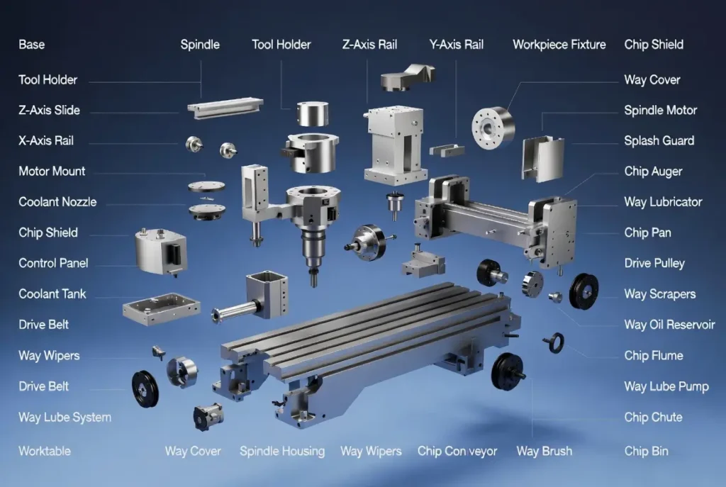
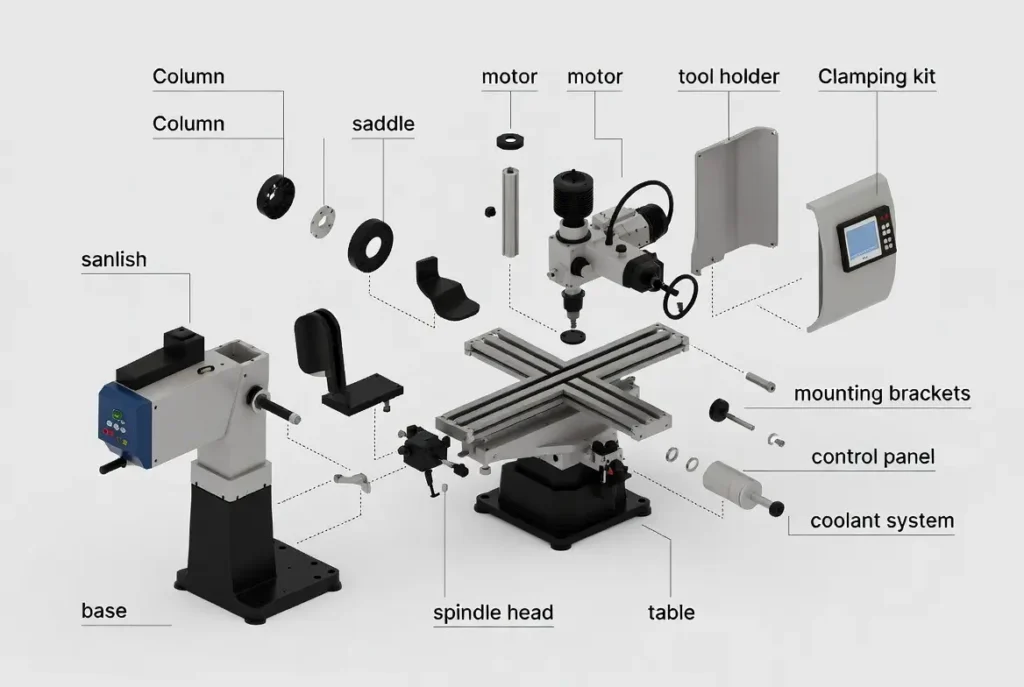
CNC Milling Machine Parts Diagram & PDF Download
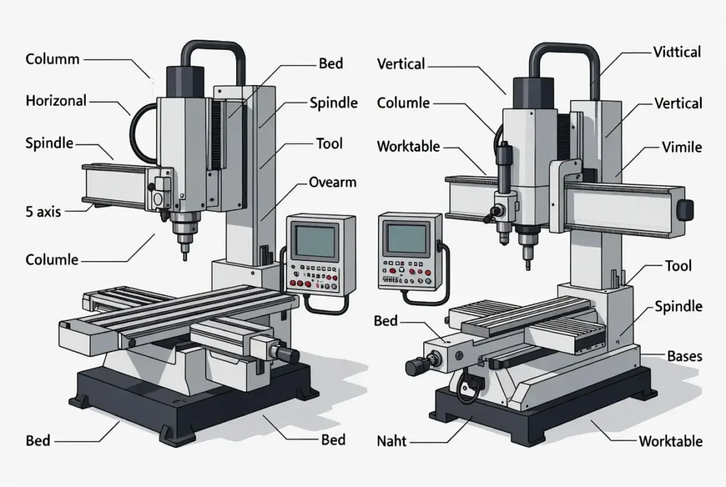
To help you visualize every component instantly, here are the clearest CNC milling machine parts diagrams available (horizontal vs. vertical labeled views plus full exploded technical drawings). These diagrams show all parts names and their functions at a glance.
Free CNC Milling Machine Parts PDF Download Click here to download the 10-page CNC Milling Machine Parts PDF Checklist (free, printable):
- Full exploded diagram with every part name labeled
- Function summary for all 10 core components
- Maintenance schedule table
- Spare parts inventory checklist
- Aluminum milling tips sheet
- Small parts machining guidelines
(This PDF is optimized for shop floor use and covers exactly the keywords “cnc milling machine parts pdf”, “diagram”, “all parts name”, and “main parts”.)
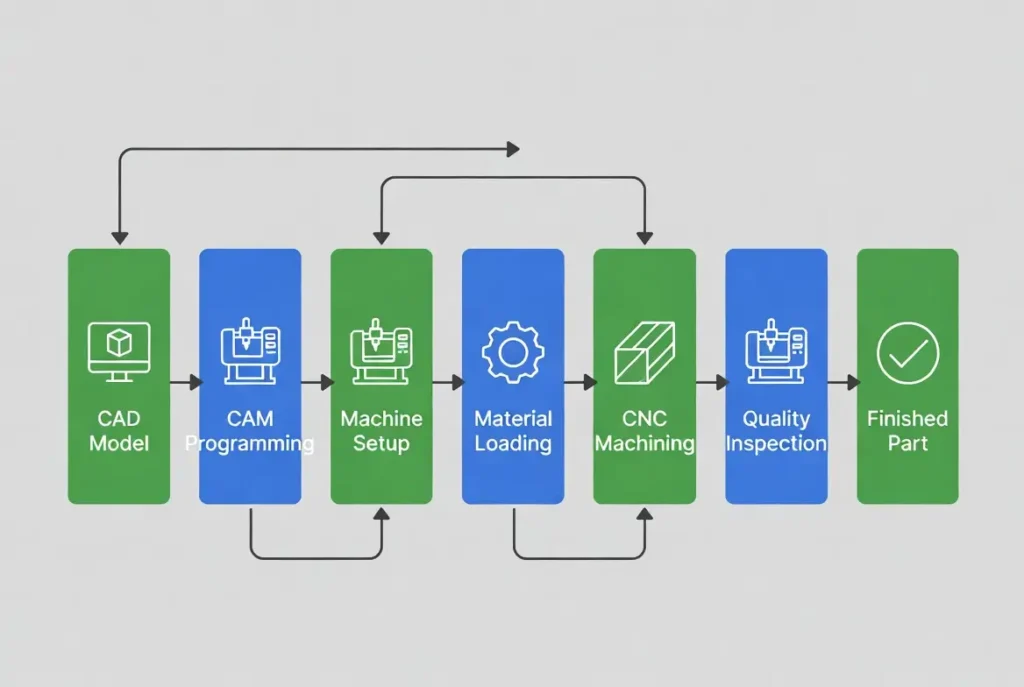
How These Parts Work Together (Step-by-Step Flow)
Here is the complete closed-loop journey from raw stock to finished part, with common pitfalls and prevention strategies:
- CAD Design → Engineer creates detailed 3D model with material properties and tolerances.
- CAM Programming → Toolpaths generated with optimized speeds/feeds; dynamic simulation detects collisions. Pitfall: Incorrect chip load—solution: use manufacturer tool libraries.
- G-Code Generation → Post-processor tailors code to specific controller.
- Setup → Workpiece fixtured, tools loaded, tool-length and work offsets measured with probe.
- Cycle Start → Controller executes line-by-line; servos drive ball screws, spindle spins at commanded RPM, coolant floods, ATC swaps automatically.
- Real-time Feedback → Encoders and in-process probes correct position every millisecond; adaptive algorithms adjust for tool wear.
- Chip Evacuation & Finishing → Conveyor removes debris; optional on-machine probing verifies dimensions before next operation.
This closed-loop architecture is why modern CNC mills achieve 99.99% repeatability and enable true lights-out production.[1]
Types of CNC Mills and Part Variations
Vertical Machining Centers (VMCs)
Most common for general-purpose work. Spindle perpendicular to table. Parts variations include lighter columns and simpler ATCs. Ideal for plates, molds, and 3-axis jobs.
Horizontal Machining Centers (HMCs)
Spindle parallel to floor for gravity-assisted chip evacuation. Heavier beds, reinforced ways, and pallet changers enable unmanned 24/7 operation. Perfect for engine blocks and transmission cases.
5-Axis CNC Mills
Two additional rotary axes (A/C or B/C) allow single-setup machining of complex parts. Components feature reinforced columns and high-torque rotary tables. Dramatically reduces setups and improves surface finish on undercuts.[6]
Additional Types: Gantry & Desktop
- Gantry Mills: Massive bridge-style structure for very large parts (e.g., aerospace panels). Extra-long linear guides and dual-drive systems.
- Desktop/Mini Mills: Compact for prototyping and education. Smaller spindles (up to 10,000 RPM) and lighter ball screws but surprisingly high precision (±0.01 mm) — perfect for cnc milling small parts and cnc milling machine for small parts.
Comparison Table (text): Vertical: Lower cost, easy access, best small-medium parts. Horizontal: Superior rigidity & chip flow, high-volume prismatic. 5-Axis: Ultimate versatility, aerospace/medical. Gantry: Largest work envelope. Desktop: Affordable entry, education/prototyping.
Pro Selection Tip: 80% of job shops start with 3-axis VMC + rotary table add-on. Move to full 5-axis only when 5-sided work exceeds 30% of revenue.
Design, Selection & Maintenance Considerations
DFM (Design for Manufacturability) – 10 Golden Rules
- Wall thickness ≥0.8 mm metal / 1.5 mm plastic.
- Pocket depth ≤3× tool diameter.
- Internal corner relief 0.5–1 mm.
- Use standard tool diameters (¼”, ½”, etc.).
- Minimize setups with 5-axis thinking.
- Avoid thin floors that vibrate.
- Add draft angles for deep features.
- Design for probing access.
- Specify realistic tolerances (±0.05 mm unless critical).
- Group similar features for fewer tool changes.
Common Problems & Solutions
- Tool Breakage → Incorrect feeds/speeds or runout. Solution: Use dynamic toolpath software + runout <0.005 mm.
- Chatter/Vibration → Poor fixturing or worn guides. Solution: Add dampening pads; check preload.
- Overheating → Inadequate coolant or high-duty cycle. Solution: Through-tool coolant + spindle chiller.
- Backlash → Worn ball screws. Solution: Replace every 8,000–12,000 hours or when positioning error >0.01 mm.[4]
- Calibration Drift → Thermal expansion. Solution: Daily probing routine + temperature-controlled shop (20±2°C ideal).
- Thermal Drift → Solution: Spindle chiller + shop at 20±2°C.
- Encoder Drift → Solution: Annual calibration.
- Coolant Bacterial Growth → Solution: Weekly biocide + filtration upgrade.
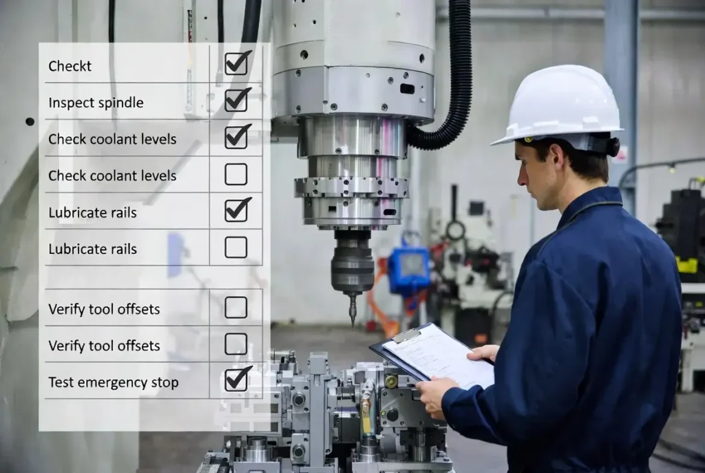
Maintenance Checklist – 2025 Best Practices
Daily (5 min): Clean, lube check, chip removal, visual leaks. Weekly: Spindle runout, way wipers, air filters. Monthly: Ball-screw backlash test, coolant deep clean, alignment check. Quarterly: Full geometric laser calibration, bearing temperature mapping. Annual: Professional spindle rebuild evaluation.
Predictive Maintenance Strategy: Install vibration sensors + IoT dashboard. AI algorithms now predict spindle failure 30–60 days in advance, cutting unplanned downtime 50%.[5]
Upgrade Recommendations (2025):
- AI predictive module (ROI 6–9 months).
- 1,000 psi through-tool coolant for titanium.
- Linear motors for 60 m/min rapids.
- Ceramic hybrid spindles for 50,000 RPM.
CNC Milling Machine Spare Parts Guide
One of the most searched topics is cnc milling machine spare parts — here is your complete 2025 buying and stocking guide.
Top 10 Most Common Spare Parts (with typical lifespan & cost)
- Spindle bearings (ceramic hybrid) — 8,000–15,000 hours / $300–$800
- Ball screws & nuts — 10,000–20,000 hours / $800–$2,500
- Linear guide blocks & wipers — 15,000 hours / $150–$400 per axis
- ATC gripper arms & sensors — 50,000 cycles / $200–$600
- Coolant pumps & filters — 2–3 years / $250–$900
- Drawbar assemblies — 5–7 years / $400–$1,200
- Encoder & servo cables — 3–5 years / $100–$300
- Way wipers & seals — replace yearly / $50–$150
- Lubrication pump & distribution blocks — 4–6 years / $300–$700
- Tool magazine proximity sensors — 2–4 years / $80–$200
OEM vs Aftermarket Recommendation
- Use OEM (Haas, DMG Mori, Fanuc) for critical parts (spindle, ball screw) to maintain the warranty.
- Aftermarket (NSK, THK, Hiwin) for guides, wipers, and coolant pumps — saves 30–50% with same performance.
Stocking Strategy for Small Shops Keep 1 spare set of: spindle bearings, 1 set of linear guide wipers, 2 coolant filters, and 1 ball screw nut. Total cost under $2,000 — prevents 90% of emergency downtime.
Where to Buy
- Official OEM portals (Haas Parts, DMG Mori Spare Parts)
- Industrial suppliers: MSC Industrial, Grainger, Amazon Industrial
- Specialized: ITS CNC, CNC Depot, or local rebuilders
Pro Tip for CNC Milling Aluminum Parts: Always keep extra coolant nozzles and high-pressure pump seals — aluminum chips clog systems faster.
Applications & Real-World Examples
Aerospace: Boeing and Airbus machine titanium spars and aluminum frames on 5-axis mills. NASA uses them for heat-resistant turbine blades. Thompson Aero Seating cut seat-rail cycle time 48% (61 → 32 min).
Automotive: Ford and Tesla rely on HMCs with pallet changers for EV battery housings and engine blocks. Tata Motors reduced EV powertrain weight 15% via optimized CNC aluminum parts.
Medical: 5-axis machines produce titanium hip implants and surgical tools with organic contours. One U.S. implant maker achieved 99.98% first-pass yield using in-process probing.
Mold & Die / Electronics: Complex cooling channels in smartphone molds. Defense and energy sectors machine missile components and turbine blades with sub-micron accuracy.
Additional Industries: Jewelry (micro-milling), semiconductor (wafer fixtures), renewable energy (wind-turbine hubs), and cnc milling small parts for medical devices and consumer electronics prototypes.
Future Trends in CNC Parts (2025–2035)
- AI & Machine Learning — Predictive maintenance cuts downtime 50%; real-time adaptive toolpaths adjust every 50 ms.[5] Timeline: 2025 widespread adoption, 2030 fully autonomous cells.
- IoT & Digital Twins — Virtual replicas enable remote simulation and zero-downtime updates.[7]
- Hybrid Additive-Subtractive — Print near-net blanks then finish-mill, saving 30–40% material on titanium.
- Advanced Materials — Ceramic spindles, carbon-fiber beds, diamond-coated tools for 50,000+ RPM.
- Sustainability — Energy-recovery drives, MQL dry machining, recyclable coolants reduce carbon footprint 25%.[8]
- Ultra-Precision & Micro-Machining — Sub-micron tolerances for optics and semiconductors; cobots for lights-out operation — perfect for cnc milling small parts.
By 2035, expect fully autonomous “lights-out” factories where one technician oversees 50+ connected 5-axis cells producing zero-defect parts 24/7.
FAQs
Q1: What are the main parts of a CNC milling machine?
Bed, column, spindle, tool changer, worktable, linear guides, ball screws, controller, coolant system, and lubrication.
Q2: How often should I maintain a CNC mill?
Daily cleaning/lube check, weekly inspections, monthly deep cleans, and annual professional alignment.
Q3: What’s the difference between vertical and horizontal CNC mills?
Vertical = easier access and lower cost; Horizontal = better chip evacuation and suited for high-volume prismatic parts.
Q4: How much does a 5-axis CNC mill cost?
Entry-level ~$150k–$300k; production-grade $400k–$1M+.
Q5: What causes chatter in CNC milling?
Worn tools, improper feeds/speeds, poor fixturing, or loose machine components.
Q6: Can CNC mills machine titanium?
Yes—with high-pressure coolant, rigid setups, and carbide or ceramic tools at lower speeds.
Q7: What is the most important part for accuracy?
The spindle (runout) and linear guides/ball screws (backlash control).
Q8: How long do CNC machine parts last?
Spindles 8,000–15,000 hours; ball screws 10,000–20,000 hours with proper maintenance.
Q9: Is AI coming to CNC machines?
Absolutely—predictive maintenance and adaptive toolpaths are already shipping on premium models.
Q10: Where can I buy replacement CNC parts?
OEM (Haas, DMG Mori), aftermarket suppliers, or specialized rebuilders.
Conclusion
Mastering CNC milling machine parts—not just buying the latest machine—is the true path to world-class accuracy, speed, and profitability. Invest in rigid beds, ceramic spindles, preloaded guides, proactive predictive maintenance, and continuous training, and your shop will outperform competitors for decades.
Immediate 30-Day Action Plan (expanded):
- Audit all 10 components against the checklists above.
- Implement daily 5-minute routine this week.
- Schedule spindle health check + vibration analysis within 14 days.
- Add one 5-axis rotary table or AI module in the next 6 months.
- Download the free PDF checklist and start your spare parts inventory.
The future of manufacturing is already here—and it is built from perfectly understood and meticulously maintained CNC parts.
References
[1] Majano III, J. (n.d.). CNC Feed Drive Control. Cal Poly Digital Commons. https://digitalcommons.calpoly.edu/context/mesp/article/1687/viewcontent/F12_FDR.pdf
[2] Krimpenis, A.A., et al. (2023). Design and Analysis of a Desktop Multi-Axis Hybrid Milling-Additive Manufacturing System. Semantic Scholar. https://pdfs.semanticscholar.org/741f/36b2d48f848f5cdce53b66f913c064dc284a.pdf
[3] Whitican, S. (2021). Novel New Modeling Procedure for Industrial Linear Guide. Michigan Tech Digital Commons. https://digitalcommons.mtu.edu/cgi/viewcontent.cgi?article=2420&context=etdr
[4] Prasad, D. (n.d.). Methodology for Selecting Components While Fabricating a Small Scale CNC Milling Machine. International Journal of Scientific & Engineering Research. http://ijses.com/wp-content/uploads/2019/02/195-IJSES-V3N1.pdf
[5] Davies, O., et al. (2022). A Digital Twin Design for Maintenance Optimization. Procedia CIRP. https://www.sciencedirect.com/science/article/pii/S221282712200717X/pdf
[6] Roy, R., et al. (2024). Optimization of Process Parameters in CNC End Milling. IEOM Society Proceedings. https://ieomsociety.org/proceedings/bangladesh2024/48.pdf
[7] ASME. (2024). Machining Process Automation in Computer Numerical Control Turning. Journal of Manufacturing Science and Engineering. https://asmedigitalcollection.asme.org/manufacturingscience/article/146/4/041004/1195163
[8] Haiqun, Y., et al. (2024). Segmented electrochemical milling of large and difficult-to-machine parts. International Journal of Electrochemical Science. DOI: 10.1016/j.ijoes.2024.100483. https://www.sciencedirect.com/science/article/pii/S145239812400483X