This comprehensive guide covers everything from basic definitions to measurement methods, key parameters (Ra, Rz, RMS), symbols, charts, manufacturing influences, material-specific requirements, and practical optimization tips. It targets engineers, CNC operators, designers, and quality professionals.
What Is Surface Finish and Why It Matters
Surface finish, also known as surface roughness, refers to the texture or micro-irregularities on a machined, cast, or manufactured surface. These irregularities include peaks, valleys, scratches, and waviness created during the manufacturing process (e.g., turning, milling, grinding, 3D printing, or casting).
Surface finish is not just cosmetic—it directly impacts part performance, longevity, and functionality:
- Friction and wear: Rougher surfaces increase friction, leading to higher energy loss, heat generation, and premature failure in bearings, seals, or sliding contacts.
- Sealing and leakage: In fluid systems, high roughness can prevent proper sealing (O-rings, gaskets).
- Fatigue strength: Surface defects act as stress concentrators, reducing fatigue life in cyclic loading.
- Coating and adhesion: Proper roughness improves paint, plating, or adhesive bonding.
- Aesthetics and cleanability: Critical in medical, food, and optical applications.
- Regulatory compliance: Industries like aerospace, medical devices, and automotive enforce strict standards (ASME B46.1, ISO 4287, etc.).
Core Concepts of Surface Texture
Surface texture consists of three main components (per ISO 4287):
- Roughness (Ra, Rz, etc.) — Short-wavelength irregularities from tool marks or cutting edges.
- Waviness — Medium-wavelength deviations caused by machine vibration, deflection, or thermal effects.
- Lay — Directional pattern of the texture (parallel, perpendicular, circular, radial, etc.).
Surface roughness differs from flatness (macroscopic deviation from a plane) and form error. Understanding these helps avoid common design mistakes.
Key Surface Roughness Parameters Explained
Ra (Arithmetic Average Roughness)
Ra is the most widely used parameter worldwide. It is the arithmetic mean of the absolute values of profile deviations from the mean line over the sampling length.
Formula (simplified): Ra = (1/L) ∫|z(x)| dx from 0 to L
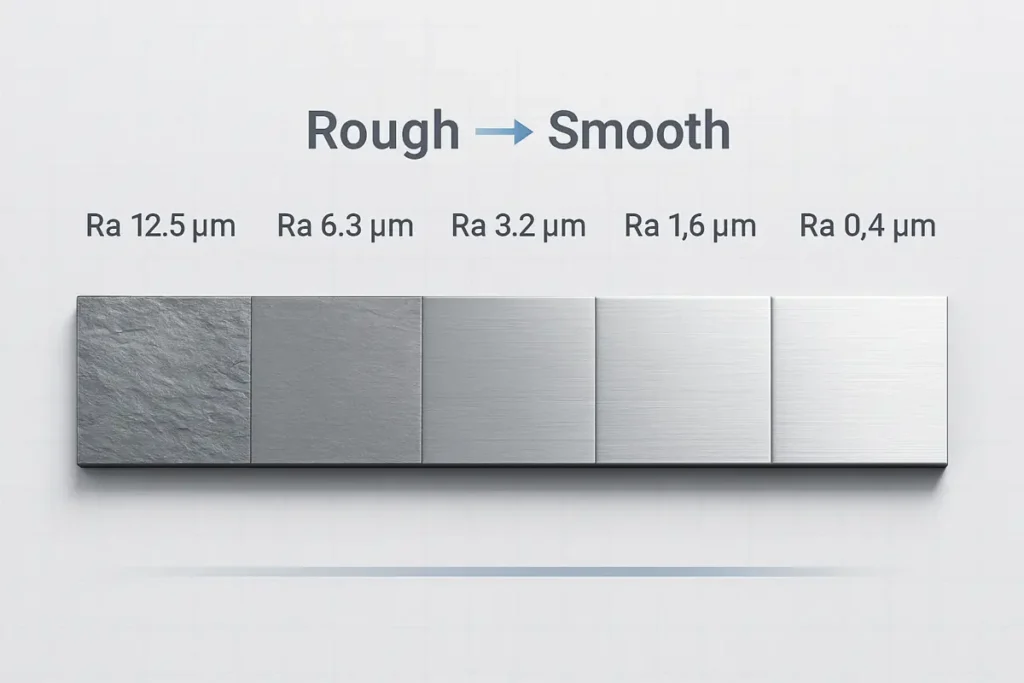
Lower Ra = smoother surface. Common values:
- Ra 0.025–0.1 μm: Mirror/polished (optics, medical implants)
- Ra 0.4–1.6 μm: Fine machined (precision bearings)
- Ra 3.2–6.3 μm: Standard machined parts
- Ra 12.5+ μm: Rough cast or as-forged
Ra is simple and robust but insensitive to peak/valley shape.
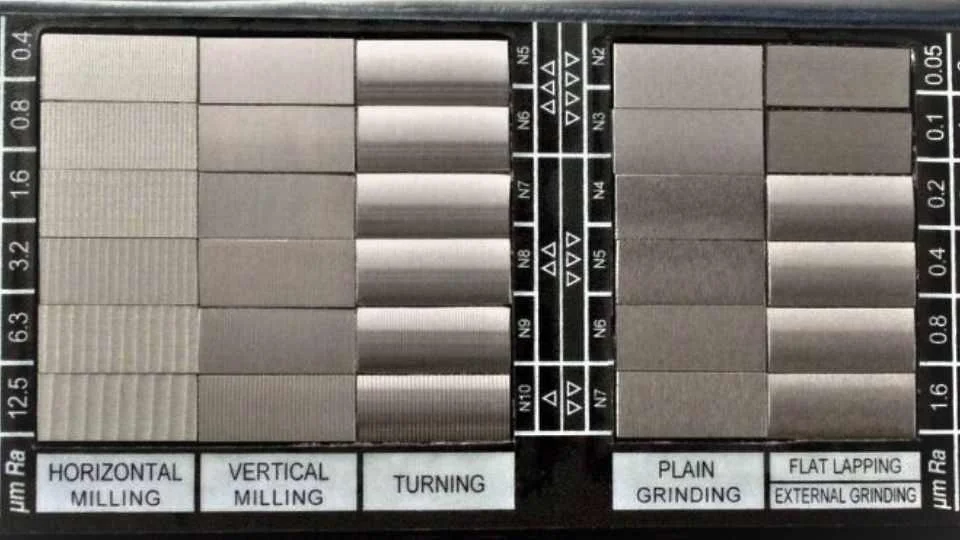
(Visual: Surface roughness comparator showing real machined samples at different Ra levels.)
Rz (Maximum Height of the Profile)
Rz averages the distance between the highest peak and deepest valley across five sampling lengths. It is more sensitive to extreme features and better for sealing or fatigue-critical applications.
Typical ratio: Rz ≈ 4–7 × Ra (depending on process).
Rq / RMS (Root Mean Square Roughness)
Rq is the root mean square of deviations—statistically more representative for Gaussian-like profiles.
Rq ≈ 1.11 × Ra (approximate conversion).
Used in optics, vibration analysis, and some aerospace specs.
Other Important Parameters
- Rt: Total profile height (single sampling length max peak-to-valley)
- Rp: Maximum peak height
- Rv: Maximum valley depth
- Rsk (skewness): Indicates whether surface is peak-heavy or valley-heavy
- Rku (kurtosis): Measures “spikiness”
Conversion reference table:
| Parameter | Description | Typical Ratio to Ra | Use Case |
|---|---|---|---|
| Ra | Arithmetic average | 1× | General purpose |
| Rz | Max height (5-sample avg) | 4–7× | Sealing, fatigue |
| Rq (RMS) | Root mean square | ~1.11× | Optics, statistical analysis |
| Rt | Total height | 5–10× | Defect detection |
Surface Finish Symbols and Standards
Surface finish is specified on engineering drawings using standardized symbols (ISO 1302, ASME Y14.36).
Basic symbol: √ (check mark-like)
- No horizontal bar: Material removal allowed
- Horizontal bar: Material removal prohibited
- Circle: All-around surface
Common annotations:
- √ 3.2 = Ra ≤ 3.2 μm
- √ Ra 1.6 / Rz 6.3 = Dual spec
- Lay symbols: = (parallel), ⊥ (perpendicular), ⊙ (circular)
Standards overview:
- ISO 4287/4288: Defines parameters and sampling
- ASME B46.1: U.S. surface texture standard
- SPI (Society of Plastics Industry): For injection molding (A1 mirror → D3 rough)
- VDI 3400: German mold/texture reference
How to Measure Surface Finish
Measurement ensures compliance and quality control.
Contact Methods (Most Common)
Touch-probe profilometers (stylus instruments) trace the surface.
Popular models: Mitutoyo SJ series, Taylor Hobson, Mahr Pocket Surf.
Steps:
- Select cutoff length (usually 0.8 mm for Ra 0.8–3.2 μm)
- Calibrate
- Take multiple traces (average 3–5 readings)
- Report Ra, Rz, etc.
Non-Contact Methods
Laser triangulation, white-light interferometry, confocal microscopy. Ideal for soft/delicate surfaces.
Units: Micrometers (μm) or microinches (μin). Conversion: 1 μm = 39.37 μin.
Influence of Manufacturing Processes on Surface Finish
Typical Ra values by process:
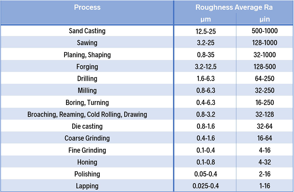
Typical Average Roughness values for various machining operations
(Visual: Comprehensive chart of average Ra values for common machining operations.)
| Process | Typical Ra (μm) | Typical Ra (μin) | Notes |
|---|---|---|---|
| Sand Casting | 12.5–25 | 500–1000 | As-cast rough |
| Milling | 0.8–6.3 | 32–250 | Depends on feed/speed |
| Turning | 0.4–6.3 | 16–250 | Tool nose radius critical |
| Grinding (fine) | 0.1–0.4 | 4–16 | High precision |
| Honing | 0.1–0.8 | 4–32 | Cylinder bores |
| Polishing/Lapping | 0.025–0.4 | 1–16 | Mirror finish |
| 3D Printing (as-built) | 10–50 | 400–2000 | Requires post-processing |
Formulas (approximate):
- Turning: Ra ≈ f² / (32 × r) where f = feed rate and r = nose radius
Material-Specific Surface Finish Considerations
- Stainless Steel: 2B (cold rolled) Ra ~0.1–0.5 μm; No. 4 brushed Ra 0.4–1.0 μm
- Aluminum: Anodized Ra 0.8–3.2 μm
- Plastics (Injection Molding): SPI A1 (diamond polish) Ra <0.1 μm → SPI D3 (bead blast) Ra ~12 μm
- PCB Finishes: ENIG Ra < 0.5 μm for solderability
Industry Applications & Typical Requirements
- Aerospace: Ra <1.6 μm for aerodynamic surfaces
- Medical Devices: Ra 0.2–0.8 μm (biocompatibility, cleanability)
- Automotive: Ra 3.2–6.3 μm for engine components
- Pharma/Biotech: ASME BPE Ra <0.38 μm for vessels
Conversion Tables & Calculators
Quick reference:
| Ra (μm) | Ra (μin) | Approx. Rz (μm) | Grit Equivalent (approx.) |
|---|---|---|---|
| 0.025 | 1 | 0.1 | 2000+ |
| 0.4 | 16 | 1.6–2.5 | 600 |
| 1.6 | 63 | 6.3–10 | 240 |
| 3.2 | 125 | 12.5–20 | 120 |
| 6.3 | 250 | 25–40 | 80 |
| 12.5 | 500 | 50–80 | 60 |
Ra to RMS: RMS ≈ Ra × 1.11 μm to μin: Multiply by 39.37
Tips to Improve / Optimize Surface Finish
- Use larger tool nose radius
- Reduce feed rate
- Increase spindle speed
- Apply coolant/lubrication
- Minimize vibration (rigid setup)
- Post-process: polishing, honing, electropolishing, vapor smoothing (for 3D prints)
Common issues: Chatter marks → solve with balanced tooling or lower depth of cut.
Quick FAQ
What does “Ra surface finish” mean?
Arithmetic average roughness—lower number = smoother.
What is a 125 surface finish?
Ra ≈ 3.2 μm (125 μin), a common machined standard.
How to convert Ra to RMS?
Multiply Ra by ≈1.11.
What tool measures surface finish?
Profilometer (contact) or optical/non-contact scanners.
How to get a better 3D print surface finish?
Chemical smoothing, sanding, or vapor polishing.
Conclusion
Mastering surface finish is essential for functional, reliable, and high-performance parts. By understanding parameters like Ra surface finish, reading symbols correctly, choosing appropriate processes, and measuring accurately, you can significantly improve product quality and reduce costs.