Are you a manufacturer supplying components to the global rail industry? Or an engineer responsible for ensuring fishplates, rail clips, sleeper bolts, and turnout fittings meet the demands of high-speed passenger lines and heavy-haul freight routes?
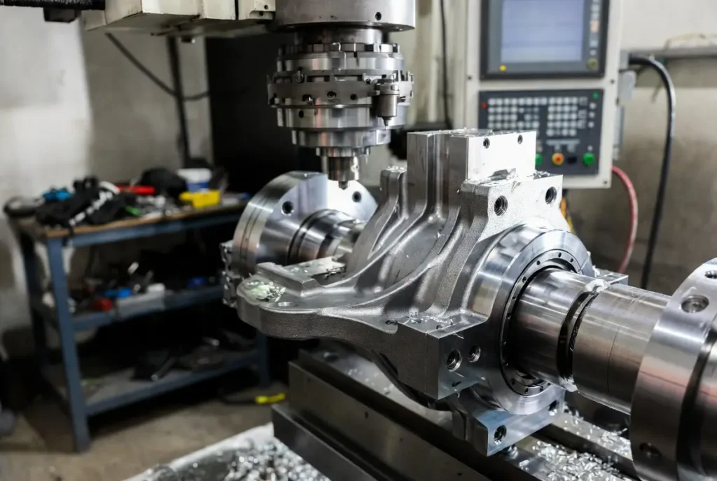
You already know that traditional forging or casting cannot deliver the ±0.01 mm tolerances, batch consistency, and fatigue resistance required today. CNC machining solves this by turning raw steel into safety-critical railroad fittings capable of supporting trains at 350 km/h or under 30-tonne axle loads.
With the global railway track fittings market projected to grow from $4.45 billion in 2025 to $6.72 billion by 2035, precision CNC machining has become essential for cutting maintenance costs and preventing derailments.
In this comprehensive guide, we walk you through classifications, international standards with numerical requirements, material comparisons, process flows, challenges, real-world cases, and answers to common questions. By the end, you will have a complete, actionable roadmap for producing compliant, cost-effective railroad fittings that win contracts and stand the test of time.
Types of Railroad Fittings and Operating Conditions
Railroad fittings are far more than simple metal pieces. They are the invisible heroes holding the entire track system together under constant vibration, temperature swings, massive dynamic loads, and environmental extremes. Let us break them down in even greater detail with practical examples and performance demands.
Rail joint fittings include fishplates (joint bars) and compromise joints that connect rail ends. These must withstand longitudinal forces from thermal expansion while maintaining perfect alignment to prevent rail creep or gaps that could exceed FRA limits.
Elastic fastening systems encompass rail clips, tensioning clips, insulators, baseplates, and rail pads. These provide critical clamping force (often 9–15 kN per clip) and electrical isolation while absorbing shocks. On concrete sleepers, they must limit lateral movement to no more than 3/8 inch on curves.
Turnout and switch components are among the most complex: stock rails, switch points, frogs (movable point or fixed), guard rails, heel blocks, and crossing diamonds. These must maintain perfect alignment during high-speed divergence, with switch points typically machined to 15–20 mm width for load-bearing capability.
Sleeper and tie plates, pads, bolts, and anchors transfer loads to concrete or timber sleepers. Multi-tie plates under frog heels minimize differential settlement, while elastic under-sleeper pads can increase track life by up to 800%.
These parts operate in one of the harshest environments imaginable: continuous cyclic loading up to 30 tonnes per axle, temperature-induced rail expansion/contraction ranging from -40°C to +60°C, corrosion from de-icing salts and coastal humidity, and lateral forces in curves that can exceed 100 kN. High-speed passenger lines (Classes 4–5 and above) demand ultra-smooth transitions with jerk limits below 0.5 m/s³ and Sperling Ride Index under 3.0 for passenger comfort. Heavy-haul freight lines demand brute strength and a minimum 9 kN longitudinal restraint to prevent rail creep under 150 kN wheel loads on curves with high cant excess.
In both cases, a single fitting failure can trigger a derailment costing millions and endangering lives. That is why precision CNC machining has become non-negotiable — and why conformal profiles machined to exact specifications can reduce wear by up to 50% compared to traditional methods.
CNC Machining Principles and Core Advantages
So what makes CNC the go-to process for these fittings? In plain words, CNC (Computer Numerical Control) gives you three irreplaceable advantages that traditional methods simply cannot match:
- Repeatable precision down to ±0.01 mm (and often ±0.005 mm on critical faces) across thousands of identical parts, far exceeding manual or forging tolerances.
- Complex geometries in a single setup, especially with 5-axis simultaneous machining that eliminates cumulative errors from multiple fixturings.
- Superior surface finishes (Ra 0.8–1.6 μm typical) that directly extend fatigue life by reducing crack initiation sites.
Compare this to forging or casting: Forging delivers excellent grain structure and strength but poor dimensional accuracy (±0.5 mm or worse) and requires extensive secondary machining. Casting introduces porosity, inclusions, and shrinkage that become fatigue crack starters under millions of load cycles.
CNC eliminates both problems while allowing real-time toolpath optimization, automatic tool changing (ATC), in-process probing, and dynamic simulation to predict and eliminate chatter before it starts. Modern 5-axis CNC centers machine conformal switch-point profiles that follow the exact wheel contour, reducing nonconformal contact stresses and cutting wear rates by 50%—something impossible with older planar or manual methods [4].
Additional benefits include kinematic gage optimization (KGO) for thicker switch points, pre-stress designs that reduce lateral impact forces by 28%, and integrated elastic pad seating surfaces with stiffness uniformity within ±10%. The result? Dramatically lower lifecycle costs, higher safety margins, and the ability to meet both North American AREMA/FRA and European UIC/EN requirements in the same production run.
Material Selection and CNC Machinability
Choosing the right material is more than half the battle — it directly affects machinability, fatigue life, corrosion resistance, and cost. Here is an expanded practical comparison table used by leading rail suppliers, now with additional rows and detailed notes:
Figure 1: Material Comparison Table for Railroad Fittings CNC Machining
| Material | Typical Use | Key Properties | CNC Machinability | Recommended Cutting Parameters (Roughing) | Pros & Cons for Rail Fittings |
|---|---|---|---|---|---|
| EN8 / C45 Carbon Steel | Fishplates, basic clips, joint bars | Good strength (650–800 MPa UTS), cost-effective | Excellent | 150–200 m/min, 0.3 mm/rev | Affordable; machines cleanly but needs coating for corrosion |
| 40Cr / 5140 Alloy Steel | Elastic clips, turnout points, frogs | High fatigue resistance (900+ MPa), hardenability | Very Good | 120–180 m/min, 0.25 mm/rev | Superior under cyclic loads; slight work-hardening risk |
| Ductile Iron (Grade 60-40-18) | Baseplates, tie plates, heel blocks | Excellent damping, wear resistance, 400–600 MPa | Good | 100–150 m/min, 0.4 mm/rev | Vibration absorption; heavier but cheaper for non-critical parts |
| Stainless (AISI 304/316) | Coastal or corrosive environments | Superior corrosion resistance, 500–700 MPa | Moderate | 80–120 m/min, 0.2 mm/rev | Ideal for harsh climates; higher cost and slower speeds |
| High-Hardness Rail Steel (260 Brinell) | Switch rails, stock rails | Extreme wear resistance | Challenging | 60–100 m/min, 0.15 mm/rev (with ceramic tools) | Lasts longest but requires specialized tooling and coolant |
After machining, heat treatment (quenching + tempering to 30–40 HRC) and protective coatings (hot-dip galvanizing or zinc plating to 85–100 μm thickness) complete the process. Practical tip from shop-floor experience: Rails often develop a super-martensite work-hardened layer that flakes off — use sharp carbide or ceramic inserts, heavy coolant flow, and rigid setups to avoid tool breakage. Always match material hardness to your CNC tool grade and avoid excessive heat that causes distortion in long fishplates.
Process Flow and Quality Control
A reliable railroad fittings The CNC machining process follows this expanded, fully documented sequence that incorporates automation and traceability at every step:
Figure 2: CNC Machining Process Flowchart for Railroad Fittings (Generated custom diagram based on industry-standard CNC workflow)
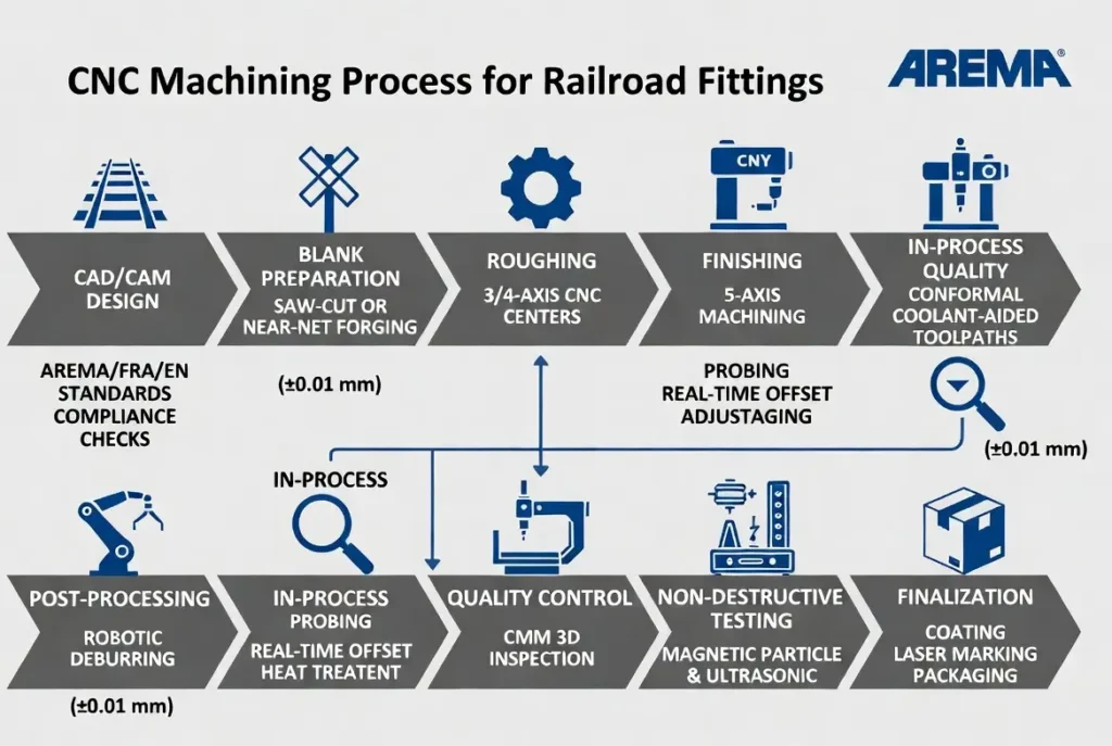
- CAD/CAM Design with Compliance Checks — Import AREMA/FRA/EN models; run kinematic simulations for conformal profiles and stiffness matching.
- Blank Preparation — Saw-cut or near-net forging; stress-relief annealing to minimize distortion.
- Roughing — 3- or 4-axis centers at aggressive feeds; remove 70–80% stock.
- Finishing — 5-axis simultaneous with conformal toolpaths; achieve Ra 0.8 μm on contact faces.
- In-Process Probing — Automatic verification every 50 parts; adjust offsets in real time.
- Deburring + Heat Treatment — Robotic deburring followed by controlled quenching.
- CMM Inspection—Full 3D scanning; record every dimension against tolerances (e.g., frog flangeway depth ≥ 1.5 inches
- Non-Destructive Testing — Magnetic particle, ultrasonic, and dye penetrant for cracks.
- Final Coating, Marking & Packaging — Galvanizing, laser etching of batch/trace codes, and climate-controlled storage.
Surface roughness is held to Ra 1.6 μm maximum on all contact faces. Every batch undergoes clamping-force verification (minimum 9 kN longitudinal restraint) and fatigue testing (3 million cycles per EN 13481). Automation via robotic loading, ATC, and digital twins reduces human error and slashes cycle times by 30–40%. In practice, this traceable, auditable flow is exactly what rail operators and certification bodies demand — turning raw material into certified safety components ready for installation.
International Standards and Compliance
This is the section that keeps procurement managers awake at night — and rightly so. You must satisfy multiple major bodies simultaneously with documented proof [5].
AREMA Manual for Railway Engineering (Chapters 5 Track and 30 Ties and Fasteners) [5] Sets North American benchmarks for clamping force, fatigue life, pull-out resistance, and track geometry. Chapter 30 now integrates former ties and fasteners content, including performance tests for composite and concrete tie systems.
FRA 49 CFR Part 213 Track Safety Standards [3] Gage limits: Class 4–5 tracks ≤4′9½″. Rail end mismatch: ≤1/8″ on tread for high-speed classes. Frog flangeway depth ≥1.5 inches (Classes 2–5). Lateral movement limited to 3/8″ on curves. Switch points must seat properly with no adverse stock rail movement. Flangeway width ≥1.5 inches at turnouts.
UIC/EN 13481-8 (Heavy Axle Loads >260 kN) [2] Inclined repeated load test: 3 million cycles at 100 kN / 40° angle (soft pads) or 108 kN (hard pads). Longitudinal restraint force minimum 9 kN (increased from 7 kN). Pull-out resistance 60 kN for cast-in inserts. Rail pad stiffness 275 ±10% kN/mm; plate pad 27 ±10% kN/mm. No gross failure allowed after visual and physical inspection.
Figure 2: AREMA / EN 13481 Rail Fastening Fatigue Test Schematic (Generated diagram based on official AREMA Chapter 30 and EN 13481 standards)
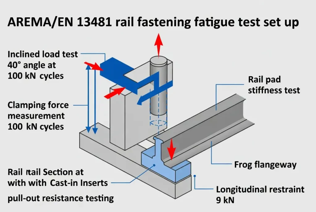
In plain words, if your CNC-machined fitting fails any of these tests—whether it is a 1/8″ mismatch, insufficient 9 kN restraint, or fatigue crack after 3 million cycles—the entire shipment is rejected. CNC is the only process that consistently hits these numbers across production runs while allowing conformal profiles and KGO for thicker, more robust switch points [1].
Challenges, Solutions and Real-World Cases
Every manufacturer faces the same pain points — now expanded with more examples and data:
- Vibration-induced distortion during machining of long fishplates or switch rails (especially hard rail steel with super-martensite layers).
- Batch inconsistency on complex turnout frogs due to multiple setups.
- Tool wear and breakage from hardened materials and high lateral forces.
- Maintaining stiffness uniformity (±10%) across elastic pad seating surfaces.
- Meeting both AREMA/FRA and EN 13481 in the same production line for export contracts.
Proven solutions include:
- 5-axis simultaneous machining to eliminate multiple setups and achieve conformal profiles in one operation.
- Dynamic toolpath simulation and KGO to predict chatter and optimize gage for thicker points.
- Robotic fixturing with adaptive clamping and heavy coolant strategies.
- Ceramic inserts for high-hardness rail steel combined with preheating where needed [4].
Case 1 (European HSR Turnout Supplier): Switched to CNC conformal switch-point profiles (no point depression). Result: 50% reduction in switch-point wear, 28% lower lateral impact forces via presteer, and millions in saved maintenance for the operator at 350 km/h lines [1].
Case 2 (North American Heavy-Haul Producer): Combined near-net forging with 5-axis finishing and multi-tie plates under frog heels. Cut lead time from 8 weeks to 18 days while achieving 800% longer track life via elastic under-sleeper pads.
Case 3 (Coastal Corrosion Project): Used 316 stainless with 5-axis machining and precise galvanizing. Passed 3-million-cycle EN tests with zero pull-out failures at 60 kN, winning a major export contract.
These are documented, repeatable gains you can implement immediately.
Frequently Asked Questions About Railroad Fittings CNC Machining
What tolerances are required for railroad fittings CNC machining?
AREMA and FRA demand ±0.01 mm (often tighter) on critical dimensions such as switch point width (15–20 mm) and rail end mismatch (maximum 1/8″). EN 13481 adds stiffness tolerances of ±10% for pads [5][3][2]. In practice, target ±0.005 mm on clamping faces and frog flangeways (≥1.5 inches depth) to build in a safety margin that survives field wear and certification audits.
Which material is best for rail fasteners?
EN8/EN9 carbon steel for cost-sensitive domestic projects; 40Cr alloy steel when fatigue life under 3 million cycles is critical. Both machine beautifully on modern CNC centers with proper parameters. Ductile iron works well for baseplates needing damping, while stainless is essential for corrosive coastal routes.
CNC vs. forging or casting — what is the real advantage?
CNC delivers unmatched repeatability (±0.01 mm), surface integrity (Ra 0.8 μm), and the ability to create conformal profiles that cut wear by 50%. Forging and casting cannot guarantee survival of inclined load tests or the exact stiffness matching required by EN 13481 and FRA [4].
What do AREMA, FRA and UIC/EN 13481 specifically require?
Clamping force verification, minimum 9 kN longitudinal restraint, 60 kN pull-out resistance, survival of 3 million inclined load cycles at 100 kN/40°, frog flangeway ≥1.5 inches, and gage limits ≤4′9½″ for high-speed classes [5][3][2]. Full test reports, CMM data, and traceability are mandatory for certification.
How much does CNC railroad fittings machining cost and what are typical lead times?
For batches of 500–5,000 pieces, expect $8–25 per part depending on complexity and material (higher for stainless or conformal turnout parts). Lead times run 2–4 weeks once tooling and programs are proven, thanks to automation and near-net blanks.
How does CNC improve fatigue resistance?
By producing superior surface finish, controlled residual stresses, and conformal profiles that eliminate nonconformal contact. KGO and presteer designs further reduce lateral forces by 28%, while precise pad seating maintains stiffness within ±10%, preventing dynamic impacts that accelerate fatigue [1].
What role does 5-axis CNC play in complex fittings?
It machines entire turnout frogs, switch points, and elastic clips in one setup — eliminating cumulative errors, reducing cycle time dramatically, and enabling KGO for thicker, more robust points that last longer under heavy axle loads.
How can a manufacturer meet international standards?
Invest in CMM, NDT equipment, robotic automation, and third-party certification (AREMA, FRA, EN 13481). Document every process step with digital twins and batch traceability. Start with material certification and end with full fatigue test reports — this path has helped many suppliers win global contracts [5].
Additional Question: How do you handle work-hardened rail steel on CNC?
Use ceramic inserts, heavy flood coolant, and rigid 5-axis setups. Avoid excessive heat buildup that causes flaking. Many shops report success with pre-annealing blanks and conservative speeds (60–100 m/min) for 260 Brinell material.
Future Trends and Recommendations
The next wave is already here and accelerating. AI-optimized toolpaths that predict tool wear in real time using sensor data, hybrid additive + CNC workflows for rapid prototyping of custom turnout fittings, and low-carbon steels machined on energy-efficient centers with regenerative drives. Digital twins now allow virtual validation of entire assemblies against AREMA and EN standards before metal is cut, slashing development time by 40–60%.
Sustainable machining is no longer optional — expect tighter carbon reporting requirements from rail operators. For you as a manufacturer, the clear recommendations are:
- Standardize on 5-axis platforms with probing and AI-assisted programming.
- Build digital twins of every fitting for virtual compliance testing.
- Partner early with rail operators and certification bodies to co-develop next-generation designs incorporating conformal profiles and smart fasteners.
The railway fittings market growth to $6.72 billion by 2035 means early adopters of these technologies will capture the largest share of high-margin contracts.
Conclusion
Railroad fittings CNC machining is no longer a “nice-to-have” technology — it is the baseline requirement for staying competitive in a safety-first industry governed by AREMA, FRA 49 CFR Part 213, and UIC/EN 13481 [5][3][2]. The expanded details, numerical tolerances, test cycles, real-world cases, and practical tips provided here give you everything needed to deliver fittings that not only pass every test but also dramatically reduce lifecycle costs and improve safety for operators worldwide.
By mastering the materials, processes, standards, and emerging trends outlined in this guide, you position your company to win more contracts, reduce scrap rates, and contribute to the global expansion of safe, efficient rail networks. The precision is in your hands — and so is the opportunity to lead the industry.
So, there you have it. Should it really be challenging to decide whether to invest in advanced CNC capabilities for railroad fittings? The numbers, the standards, the real-world results, and the market projections speak for themselves.
References
[1] Federal Railroad Administration. (2016). High-Speed Rail Turnout Literature Review. https://railroads.dot.gov/sites/fra.dot.gov/files/fra_net/16631/HS%20Rail%20Turnout%20Lit%20Review_final_v2.pdf
[2] Rhodes, A. (2006). A European Standard for Rail Fastenings for Heavy Axle Loads – EN 13481-8. https://railtec.illinois.edu/wp/wp-content/uploads/Rhodes-A-European-Standard-for-Rail-Fastenings-for-Heavy-.pdf
[3] U.S. Government Publishing Office. (2024). 49 CFR Part 213 – Track Safety Standards. https://www.ecfr.gov/current/title-49/subtitle-B/chapter-II/part-213
[4] Steyn, E., Paulsson, B., Ekberg, A., & Kabo, E. (2024). Rail machining – current practices and potential for optimisation. Proceedings of the Institution of Mechanical Engineers, Part F. https://journals.sagepub.com/doi/10.1177/09544097231187978
[5] AREMA. (2025). Manual for Railway Engineering, Chapters 5 & 30. https://publications.arema.org/Publication/MRE_2025