Precision manufacturing demands precision positioning. Understanding CNC locating pins is the foundation of repeatable, high-quality machining operations.
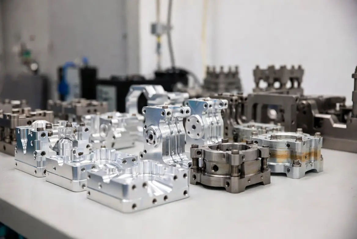
In CNC machining, the difference between a scrap part and a precision component often comes down to one seemingly simple element: the locating pin. These precision-engineered components serve as the backbone of modern workholding systems, ensuring that every workpiece occupies the exact same position—within thousandths of an inch—operation after operation, part after part.
Whether you’re designing your first fixture or optimizing a high-volume production line, this comprehensive guide covers everything from fundamental kinematic principles to advanced material selection, helping you make informed decisions that directly impact your manufacturing quality and efficiency.
What Are CNC Locating Pins?
CNC locating pins are precision-machined cylindrical components used to establish accurate, repeatable positioning of workpieces within fixtures, jigs, and tooling systems. Unlike general-purpose fasteners, locating pins are engineered specifically for dimensional accuracy, typically manufactured to tolerances of ±0.0002 inches or tighter.
The primary function of locating pins extends beyond simple alignment—they create a deterministic reference frame that eliminates variation in workpiece placement. In practical terms, this means when an operator loads a part onto a fixture with properly designed locating pins, the CNC program can execute with confidence that the cutting tool will encounter material exactly where expected.
The 3-2-1 Locating Principle: The Kinematic Foundation
Every rigid body in three-dimensional space possesses six degrees of freedom (DOF): three translational movements (X, Y, Z axes) and three rotational movements (pitch, yaw, roll). To machine a part accurately, a fixture must constrain all six degrees of freedom without over-constraining the workpiece.
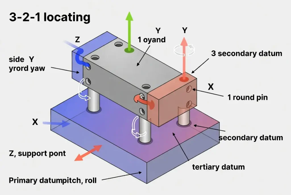
The 3-2-1 principle—also known as the six-point locating method—provides the systematic approach based on kinematic constraint theory:
• 3 points define the primary datum plane (removing Z translation, pitch, and roll)
• 2 points define the secondary datum plane (removing Y translation and yaw)
• 1 point defines the tertiary datum plane (removing X translation)
Locating pins typically serve as the 2-point secondary locators or the 1-point tertiary locator in this system, working in conjunction with support pads that establish the primary 3-point plane. According to the ASME Y14.5 standard, datum reference frames are established by the ordered set of datum features and by how those features are simulated, not by an assumed “base-plane, side-plane, end-plane” pattern. The effect of the primary, secondary, and tertiary references depends on the type of datum feature, the specified material boundary, and the intended simulator. [2]
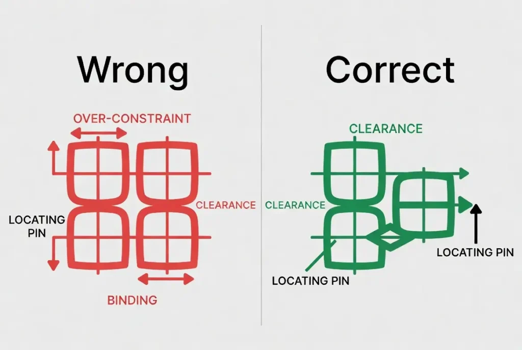
Design Insight: The 3-2-1 principle isn’t merely theoretical—it’s the difference between consistent quality and dimensional drift. Violating this principle by adding redundant locators creates “over-constraint,” where the workpiece rocks between competing reference points, producing unpredictable positioning. [1]
Types of CNC Locating Pins
Understanding the distinct types of locating pins enables designers to select components that match specific functional requirements, loading conditions, and tolerance demands.
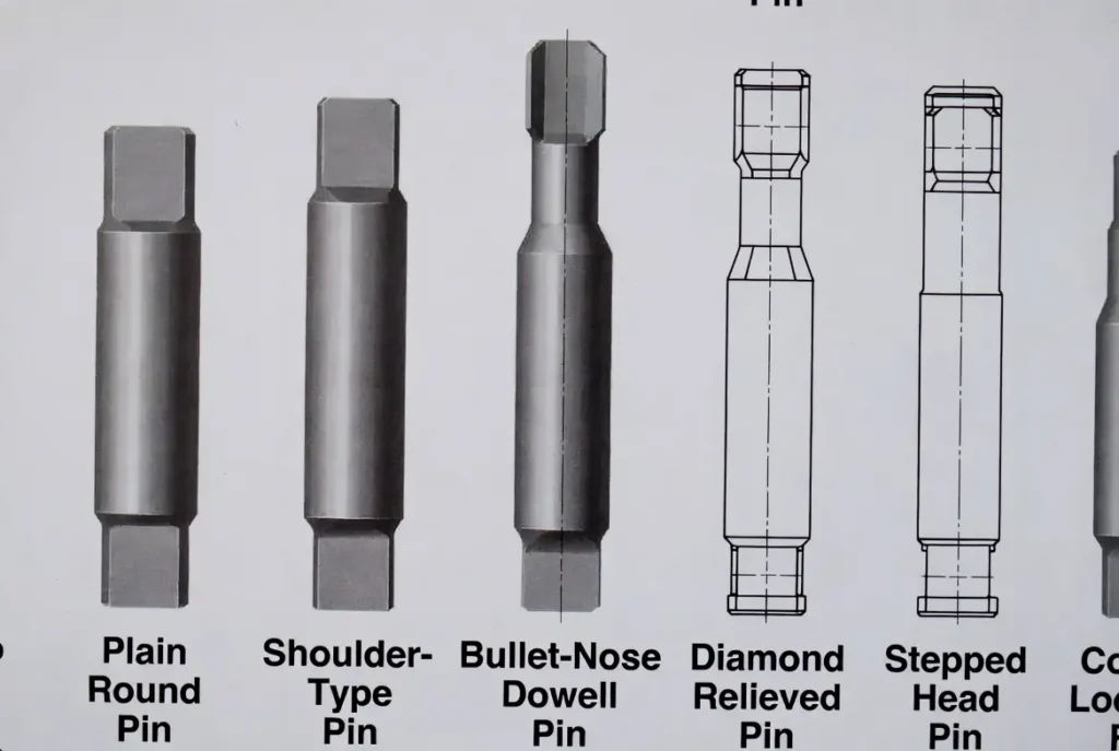
Round Locating Pins (Cylindrical Pins)
Round locating pins represent the most common configuration, featuring a cylindrical locating surface that provides equal constraint in all radial directions. These pins serve as primary locators when used singly, constraining both X and Y axes simultaneously.
Key Variants:
• Plain Locating Pins: Simple cylindrical design, typically press-fit directly into the fixture body. Best suited for short-to-medium production runs where pin replacement isn’t anticipated.
• Shoulder-Type Pins: Feature a flange or shoulder that provides Z-axis location (depth control) in addition to X-Y positioning. Available in press-fit and lockscrew configurations, with the latter using liner bushings for renewable applications.
• Bullet-Nose Dowels: Incorporate a radiused tip that facilitates easier insertion and alignment, particularly valuable in automated loading scenarios or when operator visibility is limited.
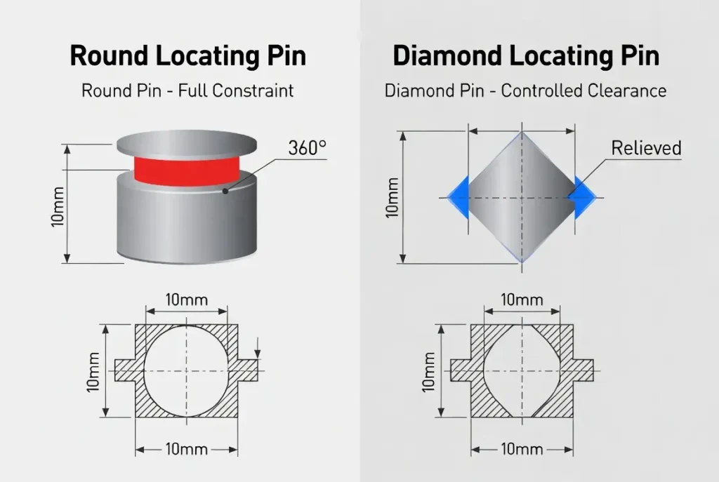
Diamond Locating Pins (Relieved Pins)
The diamond locating pin represents one of the most elegant solutions to a persistent fixture design challenge: how to locate a workpiece using two holes without over-constraining the system.
The diamond pin features four machined flats creating a diamond-shaped cross-section. This geometry provides full constraint in one axis while allowing controlled clearance in the perpendicular axis. When paired with a round pin, the combination achieves precise 2-hole location while accommodating natural tolerance variations in hole spacing. [4]
Critical Design Considerations:
• The diamond pin must be oriented correctly—the constrained axis must align with the line connecting the two pin centers
• Contact area is reduced to approximately one-third of the cylindrical surface, minimizing friction during loading
• Available in multiple pilot diameters (typically designated X, Y, Z) with varying clearance tolerances
Engineering Note: Using two round pins in two holes is a common design error. Unless hole spacing is held to unrealistic tolerances, the pins will fight each other, causing binding, part distortion, or inconsistent seating. The round-diamond combination is the industry-standard solution.
Floating Locating Pins
For applications where hole spacing tolerances exceed acceptable limits, floating locating pins provide an alternative to the diamond pin approach. These specialized components feature a mechanism that allows controlled movement (typically up to 1/8 inch) in one axis while maintaining precise location in the perpendicular axis.
Floating pins are particularly valuable when:
• Working with castings or forgings with loose tolerances
• Accommodating thermal expansion differentials
• Positioning large workpieces where hole spacing errors compound
Specialized Configurations
• Stepped Head Pins: Enable simultaneous location of two workpiece layers, common in sheet metal stacking applications
• Cone Locator Pins: Feature a tapered profile that compensates for significant misalignment, useful for quick-change pallet systems
• Height-Adjustable Pins: Allow Z-axis fine-tuning for workpiece leveling or compensating for surface variations
Material Selection and Technical Specifications
The performance and longevity of locating pins depend critically on material selection, heat treatment, and surface engineering.
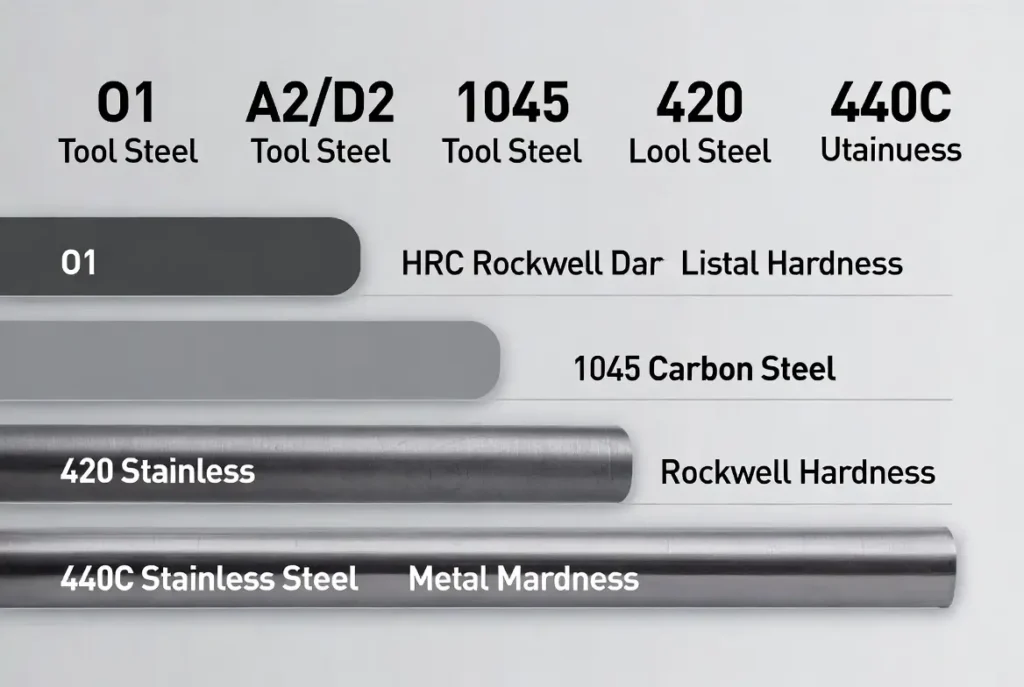
Standard Materials and Hardness
| Material | Hardness | Characteristics | Best Applications |
|---|---|---|---|
| O1 Tool Steel | HRC 60-63 | High wear resistance, dimensional stability | High-volume production, precision grinding |
| A2/D2 Tool Steel | HRC 58-62 | Air-hardening, minimal distortion | Complex geometries, tight tolerances |
| 1045 Carbon Steel | HRC 45-50 (case-hardened) | Cost-effective, good machinability | Medium-volume, general purpose |
| 420 Stainless Steel | HRC 50-55 | Corrosion resistance, moderate wear | Medical, food processing, corrosive environments |
| 440C Stainless | HRC 58-60 | High hardness + corrosion resistance | Marine, chemical processing |
Critical Insight: Soft materials (unhardened 300-series stainless, aluminum) are rarely suitable for locating pins in production environments. While they may function initially, rapid wear destroys positioning accuracy within hundreds of cycles, compromising part quality and requiring frequent replacement.
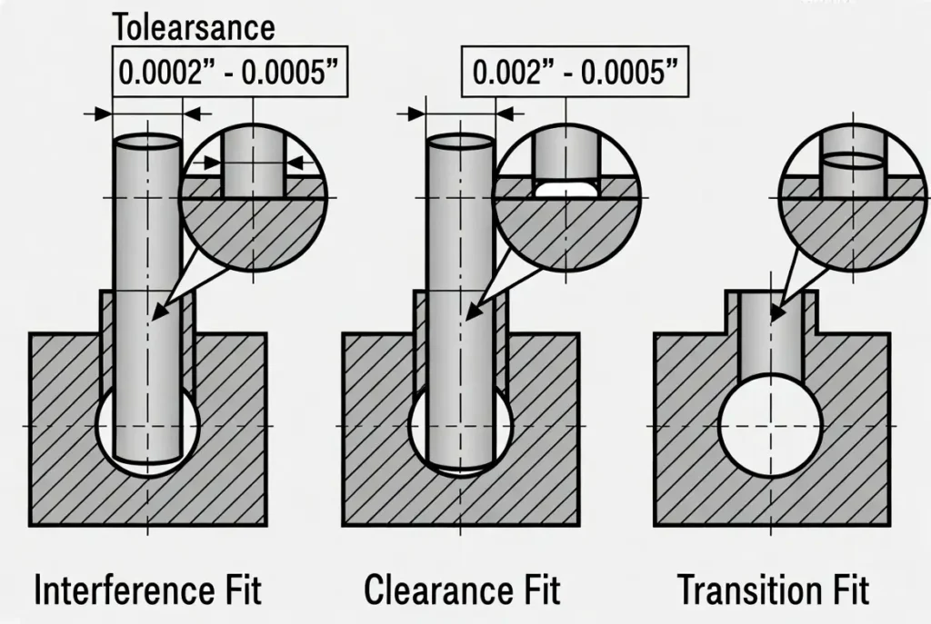
Tolerance Standards and Fit Classes
Locating pin applications typically employ three primary fit categories based on ISO 286 and ASME B4.1 standards:
Press-Fit (Interference Fit):
• Tolerance: 0.0002″–0.0005″ interference
• Application: Permanent or semi-permanent installation
• Installation: Requires arbor press or hydraulic installation • Repeatability: ±0.0002″
Slip-Fit (Clearance Fit):
• Tolerance: 0.0002″–0.0005″ clearance
• Application: Renewable pins, frequent replacement scenarios
• Installation: Hand-insertable • Repeatability: ±0.0005″
Transition Fit:
• Tolerance: Near-zero clearance/interference
• Application: Precision location with moderate renewability
• Installation: Light press or thermal methods
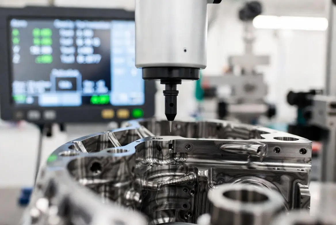
According to NIST research on precision manufacturing, high-end mechanical parts sometimes require accuracy of a few micrometers, and billions of accurate dimensional measurements performed each day guarantee that parts will fit and operate as intended. [3]
Surface Treatments and Coatings
Advanced surface engineering extends pin life and enables specialized applications:
• Hard Chrome Plating: Increases surface hardness to 70+ HRC, provides corrosion resistance, reduces friction coefficient
• TiCN (Titanium Carbonitride): Gold-colored coating offering 3000+ Vickers hardness, exceptional wear resistance for high-cycle applications
• KCF Coating: Ceramic-based insulation coating preventing weld spatter adhesion in resistance welding fixtures
• Diamond-Like Carbon (DLC): Ultra-low friction coating for delicate workpiece surfaces
Design Principles and Best Practices The Golden Rule: Pin Pairing Strategy
When locating a workpiece using two holes (the most common scenario), always implement the round-diamond pairing:
- Primary Pin (Round): Full cylindrical contact, establishes the primary datum location in X and Y
- Secondary Pin (Diamond): Relieved contact, constrains rotation only, accommodates hole spacing variation
This configuration provides complete 2D location while remaining tolerant of realistic manufacturing tolerances.
Placement Strategy
Maximize Pin Separation: Position locating pins as far apart as possible within the workpiece envelope. Greater separation improves angular accuracy and reduces the impact of individual pin tolerances on overall positioning.
Symmetrical Considerations: While symmetrical pin placement is aesthetically pleasing, asymmetrical arrangements can provide anti-rotation features and prevent 180-degree part loading errors—a form of poka-yoke (mistake-proofing) in fixture design.
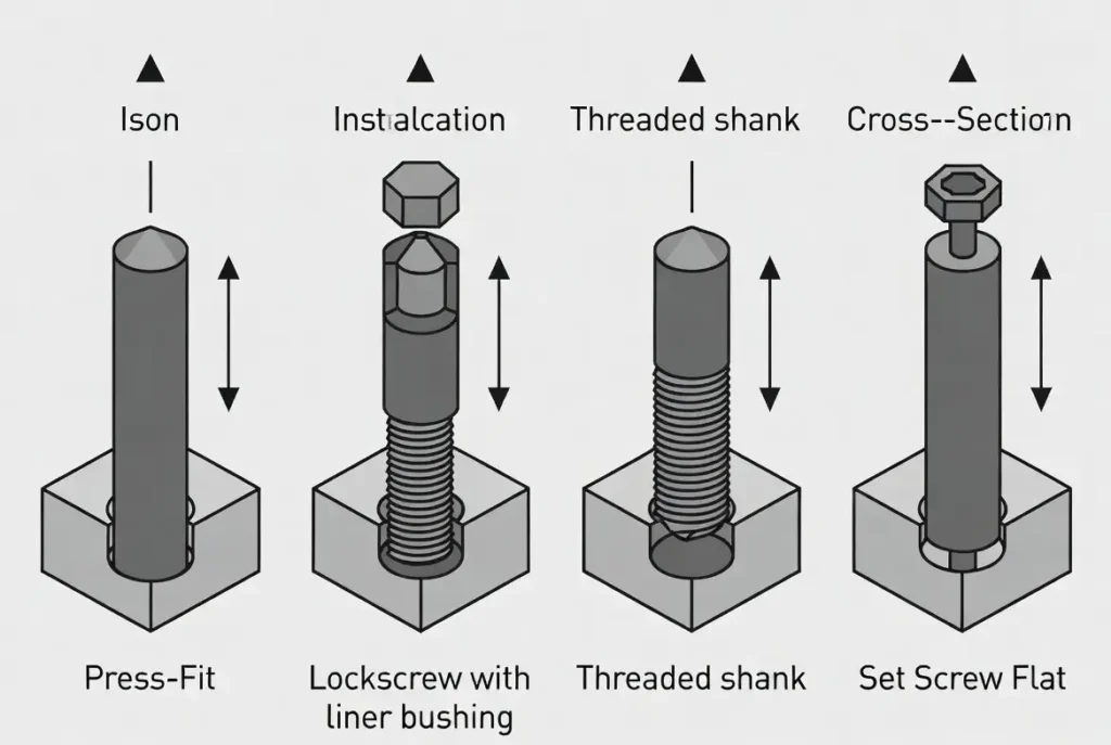
Shank Mounting Selection
| Mounting Type | Best For | Key Considerations |
|---|---|---|
| Press-Fit | Permanent installation, high vibration | Requires access to both sides for replacement |
| Lockscrew with Liner | High-volume production, renewable pins | Liner bushings protect fixture body; pins replaceable without damage |
| Threaded Shank | Limited access, adjustable height | Requires precise perpendicularity to prevent binding |
| Set Screw Flat | Quick-change applications | Flat provides anti-rotation and positive retention |
Common Design Errors to Avoid
- Over-Constraint: Using four support pads on a flat surface (only three define a plane) or two round pins in two holes creates unpredictable positioning
- Insufficient Clearance: Failing to provide air vent grooves in blind holes makes pin removal difficult or impossible due to vacuum lock
- Ignoring Chip Management: Locating surfaces near machining zones accumulate chips, causing part seating errors; implement air blow-off or strategic positioning
- Material Mismatch: Using unhardened pins in production environments leads to rapid wear and quality degradation
Applications
Automotive Body-in-White (BIW)
Automotive assembly fixtures rely heavily on locating pins for panel positioning. Round pins (often called “four-way” locators) combined with diamond pins (“two-way” locators) provide the precise location required for robotic welding operations. Research on flexible adaptive fixtures for precision grinding of thin-walled bearing rings demonstrates the critical importance of precise locating systems in automotive component manufacturing.
Aerospace Precision Assembly
Aerospace applications demand the highest precision, often using tapered locating pins with mating bushings to achieve micron-level repeatability. Temperature-compensated designs account for thermal expansion differentials between aluminum workpieces and steel fixtures.
Electronics Manufacturing
PCB assembly fixtures use miniature locating pins (2mm–6mm diameter) with precision-ground shoulders for component placement accuracy. ESD-safe coatings prevent static damage to sensitive electronics.
Semiconductor and Optomechanical Systems
Kinematic couplings—precision locating systems based on exact constraint principles—are extensively used in semiconductor manufacturing and optical instrumentation. According to research from MIT, kinematic couplings exactly constrain six degrees of freedom between two parts, enabling sub-micron repeatability in wafer positioning and optical component alignment. [1]
Installation and Maintenance Best Practices Proper Installation
- Hole Preparation: Ream mounting holes to H7 tolerance; ensure perpendicularity to the locating surface within 0.001″ per inch
- Press-Fit Technique: Use an arbor press with parallel plates; never hammer pins into place
- Lubrication: Light oil during installation reduces galling risk; remove excess before production
- Orientation: For diamond pins, verify correct orientation using the orientation flat on the flange
Air Vent Considerations
Blind holes require air vent grooves (typically a flat ground along the pin length) to prevent vacuum lock during pin removal. Without venting, hydraulic pressure makes pin extraction difficult and can damage the fixture.
Maintenance Protocol
• Daily: Visual inspection for chip accumulation; air blow-off of locating surfaces
• Weekly: Check for looseness in lockscrew-mounted pins; verify diamond pin orientation
• Monthly: Measure pin diameter at contact points; check for wear patterns indicating misalignment
• Quarterly: Replace liner bushings showing wear; recalibrate fixture datums
FAQs
What’s the difference between a dowel pin and a locating pin?
While both are cylindrical precision components, dowel pins are primarily designed for alignment and shear load transmission between mating parts. Locating pins are engineered specifically for fixture applications, with features like shoulders for depth control, specialized head shapes for easy loading, and often include renewable mounting systems. Locating pins typically achieve tighter positional tolerances than standard dowel pins.
How do I choose between round and diamond pins?
Use round pins when you need full constraint in all directions or as the primary locator in a two-pin system. Use diamond pins exclusively as secondary locators in two-pin configurations where hole spacing tolerances would cause binding with two round pins. Never use a diamond pin as a single locator—it provides insufficient constraint.
What tolerance should I use for locating pins?
For precision CNC applications, specify locating pins with ±0.0002″ diameter tolerance or better. The fit between pin and workpiece hole should typically be 0.0002″–0.0005″ clearance for slip-fit applications, or 0.0002″–0.0005″ interference for press-fit mounting.
Can I use two round pins instead of one round and one diamond?
Only if hole spacing tolerance is extremely tight (±0.0005″ or better) and you’re prepared to deal with potential binding issues. For 99% of applications, the round-diamond combination is the correct engineering solution. Two round pins constitute over-constraint and will cause problems.
How often should locating pins be replaced?
Replace locating pins when wear exceeds 0.0005″ on the locating diameter, when surface damage (galling, scoring) is visible, or when part measurements begin trending toward tolerance limits. In high-volume production (10,000+ parts), implement scheduled replacement based on statistical process control data.
What’s the best material for high-volume production?
O1 or D2 tool steel hardened to HRC 60-63 provides the best combination of wear resistance and dimensional stability for high-volume applications. For extreme volumes (100,000+ cycles), consider carbide inserts or pins with diamond-like carbon coatings.
Conclusion
CNC locating pins represent a fascinating intersection of simple geometry and sophisticated engineering grounded in kinematic constraint theory. While individual pins appear to be basic cylindrical components, their proper application requires understanding of degrees of freedom, material science, tolerance analysis, and manufacturing processes.
The difference between a mediocre fixture and an exceptional one often lies in locating pin selection and implementation. By applying the principles outlined in this guide—the 3-2-1 foundation based on kinematic constraint theory, the round-diamond pairing strategy, appropriate material selection, and diligent maintenance—you establish the foundation for manufacturing excellence.
Remember: in precision manufacturing, everything builds from the first point of contact. Make sure that point is precisely where you intend it to be.
Ready to optimize your fixture design? Start by auditing your current locating pin implementations against the principles in this guide. The improvements in part consistency and reduced setup time will validate the effort.
References
[1] Slocum, A. (2010). Kinematic Couplings: A Review of Design Principles and Applications. International Journal of Machine Tools and Manufacture, 50(4), 310-327. MIT Precision Engineering Laboratory. Retrieved from https://dspace.mit.edu/bitstream/handle/1721.1/69013/Kinematic%20coupling%20review%20article.pdf
[2] Mner, M. (2024). Technical Drawing for Product Design: Mastering ISO GPS and ASME GD&T. Engineering Design Textbook. Retrieved from https://mner.net/wp-content/uploads/2024/08/Technical-Drawing-for-Product-Design.pdf
[3] National Institute of Standards and Technology (NIST). (2025). Highly Accurate Measurements for Manufacturing at the Smallest Scale. NIST Physical Measurement Laboratory. Retrieved from https://www.nist.gov/nist-work/highly-accurate-measurements-manufacturing-smallest-scale
[4] National Institute of Standards and Technology (NIST). (1996). NIST Programs and Services: Manufacturing Engineering Laboratory. NIST Special Publication 858. Retrieved from https://nvlpubs.nist.gov/nistpubs/Legacy/SP/nistspecialpublication858e1996.pdf