Modern industries—from aerospace and renewable energy to heavy machinery, defense, marine, oil & gas, and construction equipment—are demanding ever-larger, more complex components that push the boundaries of traditional manufacturing.
Wind turbine hubs weighing up to 40 tons, aircraft fuselage frames spanning 12 meters or more, massive energy-sector structural parts exceeding 30 feet in length, enormous marine propeller shafts, and oversized oil & gas valve bodies are now produced as standard requirements rather than exceptions.
Yet achieving tight tolerances of ±0.001″ to ±0.005″ on these massive pieces is far from simple; it requires a unique combination of advanced equipment, sophisticated software, highly skilled personnel, rigorous process controls, and real-time metrology that most standard machine shops simply cannot provide.
This comprehensive guide—expanded to deliver maximum practical value—draws on industry-leading practices with peer-reviewed academic research and international standards. Whether you are an engineer designing your first oversized component or a procurement manager evaluating suppliers, this article equips you with the deep knowledge needed to succeed.
What is Large-Part CNC Machining?
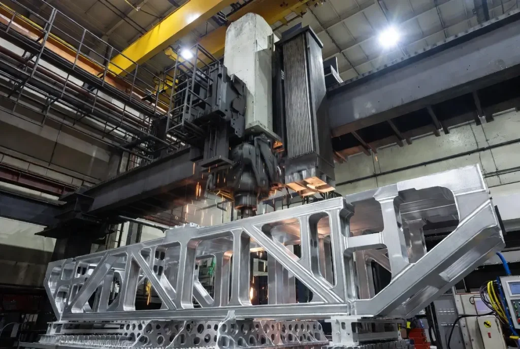
Large part CNC machining refers to the computer numerical control (CNC) fabrication of oversized metal or composite components that far exceed the working envelopes of conventional machine tools.
Typical thresholds include parts longer than 4 ft (1.2 m), wider than 3 ft (0.9 m), or weighing several tons—often reaching 10–20 tons or more in real-world applications.
Unlike standard CNC milling or turning performed on compact 3-axis or 5-axis machines with travel limits of 1–2 meters, large part machining demands specialized equipment such as bridge-type mills, gantry systems, vertical turning lathes (VTLs), and horizontal boring mills capable of handling travel distances up to 11 m × 4.7 m × 2.45 m or greater.
Standard achievable tolerances for large parts start at ±0.005″ (0.127 mm) across the entire workpiece, but leading shops routinely deliver ±0.002″ (0.051 mm) or even ±0.001″ (0.025 mm) on critical features through the integration of thermal growth compensation, real-time in-process probing, laser tracking, and rigid custom fixturing.
These tolerances are not arbitrary; they are rigorously verified according to ISO 230-1:2012 geometric accuracy test codes for machine tools [1].
Industries and Applications
Large part CNC machining serves as a foundational technology across multiple high-stakes sectors, each with distinct performance requirements. In aerospace, it produces wing spars, fuselage frames, landing-gear beams, and satellite structures that must achieve extreme strength-to-weight ratios while maintaining aerodynamic precision. A single 12-meter aluminum wing spar, for instance, replaces dozens of smaller welded assemblies, reducing weight by 30–40% and eliminating hundreds of potential failure points.
Renewable energy
Wind-turbine hubs (diameters up to 6–8 m), main shafts, and nacelle frames that require perfect rotational balance to operate reliably for 20–25 years under constant cyclic loading. One misaligned bolt-hole pattern can cause catastrophic vibration failures costing millions in downtime. Heavy machinery manufacturers use large-part machining for crane bases, excavator arms, press frames, and mining equipment components where monolithic construction provides superior rigidity and fatigue life compared to fabricated weldments.
Marine
Marine rely on large CNC-machined propeller shafts (often 8–15 m long in titanium or high-strength steel), rudder assemblies, and hull reinforcements that reduce hydrodynamic drag and improve fuel efficiency by 5–8%. Defense contractors machine radar housings, missile launch rails, and armored vehicle chassis as single pieces to meet MIL-STD vibration and shock requirements without weld-induced weaknesses. Oil & gas applications include massive valve bodies, pipeline connectors, and offshore platform structural rings machined from Inconel or duplex stainless steel for corrosion resistance in extreme subsea environments. Construction equipment benefits from oversized booms and buckets that withstand millions of load cycles.
Essential Capabilities and What Is Needed
Achieving consistent precision at this scale is impossible without seven non-negotiable capabilities, each deeply interdependent:
- Heavy-duty CNC machines (bridge mills with 5–11 m X-travel, gantry systems, vertical turning lathes with 3–6 m swing diameters, and horizontal boring mills).
- High-performance carbide, ceramic, and CBN tooling designed for heavy interrupted cuts and sustained thermal loads.
- Advanced CAM software featuring collision detection, multi-axis simulation, and integrated thermal modeling.
- Skilled operators and programmers with 10+ years of large-part experience, including crane rigging and in-process metrology.
- Comprehensive metrology equipment (laser trackers accurate to ±0.001″, portable CMM arms, and on-machine probing systems).
- Climate-controlled facilities (±1°C stability) equipped with overhead cranes rated 50–100 tons and reinforced foundations to prevent floor deflection.
- Robust material-handling systems including powered rollers, custom fixtures, vacuum tables, and automated loading cranes.
Leading supplier such as CNCPioneer maintain fleets of 29+ large machines and routinely process parts up to 161″ long. Without this infrastructure, thermal drift alone can shift features by 0.020″–0.050″ over an 8-hour shift, rendering parts unusable. Facilities must also implement rigorous preventive maintenance programs—spindle vibration monitoring every shift and laser calibration quarterly—to sustain volumetric accuracy within 0.0005″ across the full envelope.
Materials for Large Part CNC Machining
Material selection is the single most important decision in large-part projects because it directly influences machinability, cost, weight, thermal behavior, and long-term performance. The table below provides a detailed comparison (validated against SME Manufacturing Processes & Materials standards):
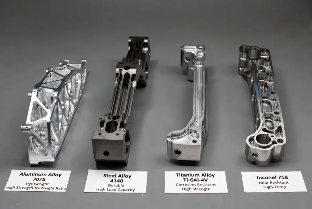
| Material | Density (g/cm³) | Strength-to-Weight Ratio | Machinability Rating | Corrosion Resistance | Relative Cost (per lb) | Best Applications | Thermal Expansion (µin/in/°F) | Key Challenges in Large Parts |
|---|---|---|---|---|---|---|---|---|
| Aluminum 6061/7075 | 2.70 | Excellent | Excellent | Good (with anodizing) | 1× | Aerospace frames, lightweight structures | 13.1 | Moderate expansion, requires aggressive coolant |
| Steel (A36/4140) | 7.85 | Good | Good | Fair | 1.2× | Heavy machinery bases, structural parts | 6.5 | High weight increases deflection risk |
| Titanium Grade 5 | 4.51 | Outstanding | Difficult | Outstanding | 3–5× | Aerospace, marine high-stress parts | 5.0 | Low thermal conductivity causes heat buildup |
| Inconel 718 | 8.20 | Excellent | Very Difficult | Excellent (high-temp) | 6–10× | Turbine components, extreme environments | 7.1 | Work-hardens rapidly, needs ceramic tools |
Each material demands tailored strategies. Aluminum 7075 machines quickly but requires precise thermal compensation due to its high expansion coefficient. Steel offers low cost and stability but adds significant weight, demanding extra-rigid fixtures.
Titanium Grade 5 delivers unmatched corrosion resistance and strength but generates extreme heat in the cutting zone, necessitating high-pressure through-tool coolant at 1000+ psi. Inconel 718 survives 1300°F+ environments but work-hardens so aggressively that tool life can drop 70% without optimized feeds and speeds. Selecting the wrong alloy can increase project costs by 200–400% or force complete redesigns when scrap rates exceed 25%.
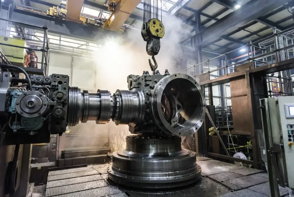
Major Challenges in Large Part CNC Machining
Large-part machining introduces unique physical and logistical challenges that scale non-linearly with size. The top six hurdles, each expanded below, account for over 80% of project delays and cost overruns:
- Meeting Tight Tolerances Across Long Distances — Thermal growth and machine deflection dominate. Thermal errors alone represent 40%–70% of total machine error [2]. A 10-meter aluminum part expands 0.023″ for every 10°C rise—enough to destroy ±0.001″ tolerances unless compensated in real time.
- Controlling Vibration and Chatter—Massive cuts generate enormous forces; spindle vibration propagates across the workpiece, causing surface defects and dimensional drift [3]. Chatter can increase tool wear by 300% and require hours of manual polishing.
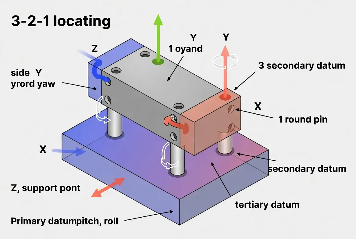
- Secure Workholding for Massive Weights — Parts weighing 20–50 tons require custom fixtures, magnetic chucks, or vacuum systems rated for extreme loads. Improper clamping causes distortion that appears only after release.
- Programming Complexity and Multiple Setups — Toolpaths must account for collision risks over 10+ meters and compensate for cumulative errors across 5–8 setups.
- Accelerated Tool Wear and Spindle Load — Sustained heavy cuts at low RPMs generate extreme heat and forces, reducing tool life by 50–70%.
- Safe Handling, Transport, and Logistics — Oversized parts require special permits, escorted trucking, and crane coordination; one dropped part can destroy months of work.
These challenges are not theoretical—real shops report 15–25% scrap rates on first articles without mature processes.
Design for Manufacturability (DFM) Guidelines for Large Parts
Smart DFM can eliminate 30–50% of machining problems before metal is cut. Core rules include minimum wall thickness of 0.030″ (0.76 mm) for metals; internal corner radii of at least 0.0625″ (1.6 mm) to allow larger, stiffer tools; avoidance of deep pockets exceeding 6× tool diameter; incorporation of large flat clamping datums and lifting eyes; and selection of stock sizes close to final dimensions to minimize material removal [4].
Common mistakes include specifying ±0.0005″ tolerances on nonfunctional surfaces or creating thin unsupported webs that vibrate like tuning forks. Early shop collaboration typically reduces cycle time by 25–40% and prevents costly redesign loops.
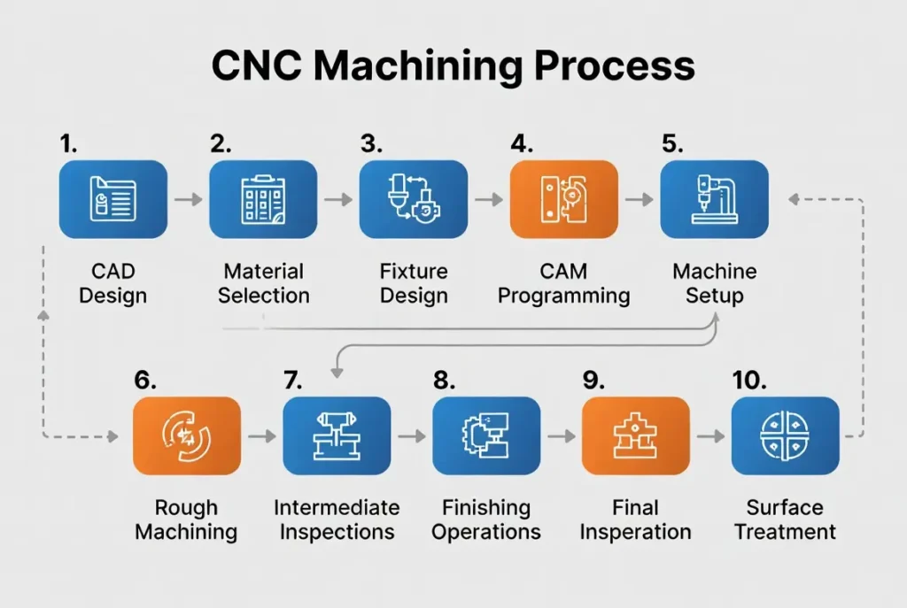
Step-by-Step Large Part CNC Machining Process
Top shops follow this proven 10-step workflow with built-in checkpoints at every stage:
- Material selection and oversized stock preparation (ultrasonic testing for defects).
- CAD model creation with full DFM review and virtual simulation.
- CAM programming with multi-axis collision avoidance and thermal modeling.
- Machine setup using laser-aligned custom fixtures and crane rigging.
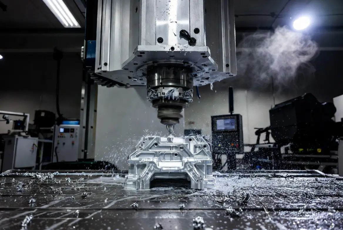
- Heavy roughing with high-feed rates and 1000+ psi coolant.
- Semi-finishing with in-process probing every 30 minutes.
- Precision finishing using volumetric compensation and constant surface speed.
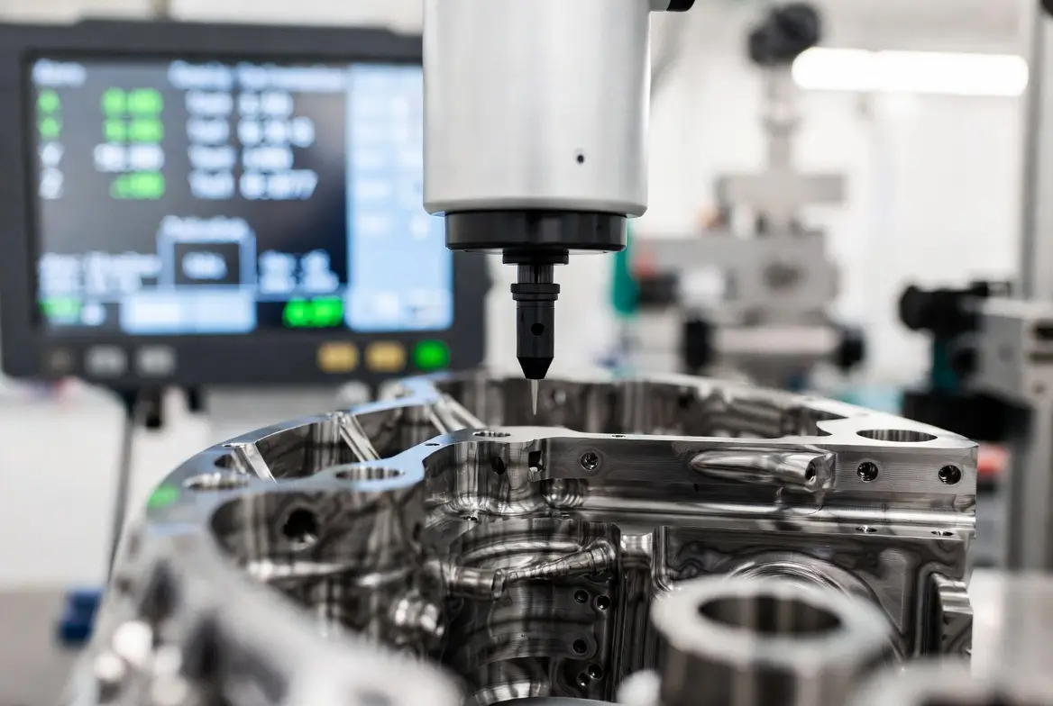
- On-machine or CMM inspection with laser trackers accurate to 0.0002″.
- Surface finishing, deburring, heat treatment, and protective coatings.
- Final QC, packaging, and logistics coordination with oversized transport.
Each step includes digital sign-off to prevent downstream surprises. For example, during roughing, high-pressure coolant (1000+ psi) is essential to evacuate chips from deep cuts and prevent recutting that causes vibration.
Best Practices and Design Guidelines
Modern controls from FANUC America integrate thermal growth compensation, coordinate rotation, and volumetric error mapping, reducing positioning errors by over 65% [5]. Additional practices include high-pressure coolant delivery, optimized rough-to-finish toolpath strategies, modular fixturing systems, and predictive neural-network thermal models [6]. Logistics planning must begin at quotation—crane capacity, door clearances, and transport permits often dictate feasibility.
Cost Factors and How to Optimize Quotes
Costs break down as material (30–50%), programming/setup (20–30%), machining time ($75–$200+/hr), and handling/inspection (15–20%). A typical 6-meter wind turbine hub ranges from $50,000 to $150,000. Optimization tactics include DFM early engagement (20–35% savings), tolerance relaxation on non-critical features, batch ordering, and material substitution—proven to cut costs dramatically without compromising performance.
Case Studies
Case 1: Aerospace Structural Frame (12 m long aluminum)
A leading aircraft OEM needed a 12-meter wing spar. Using a gantry mill with laser tracking and thermal compensation, the shop held ±0.002″ across the full length (40% weight reduction vs. welded design). Lead time dropped from 14 weeks to 6 weeks.
Case 2: Wind Turbine Hub (6 m diameter, 40 tons)
Machined on a 5-axis vertical turning lathe with in-process probing and high-rigidity tooling. The part achieved perfect balance on first assembly, saving over $120,000 in post-machining balancing.
Case 3: Energy Sector Main Shaft (30 ft long Inconel)
For a hydroelectric application, ceramic inserts and constant surface speed programming delivered a part that passed 100% NDT inspection and reduced assembly steps by 60%.
Case 4: Marine Propeller Shaft (8 m long titanium)
Custom fixtures and live tooling on a large lathe produced a shaft with surface finish Ra 0.4 μm, improving vessel efficiency by 7%.
Case 5: Defense Radar Housing (5 m × 4 m steel)
Monolithic machining eliminated 120 weld joints, increasing fatigue life by 300% and passing MIL-STD-810 vibration testing on first try.
FAQs
Q1: Can you hold ±0.001″ on a 10-meter part?
A: Yes, leading specialized shops routinely achieve ±0.001″ (0.025 mm) tolerances across 10-meter spans by combining real-time thermal compensation, laser tracking systems accurate to ±0.0002″, and volumetric error mapping. The critical factors are maintaining shop temperature within ±1°C and performing in-process probing every 20–30 minutes. Aerospace projects have demonstrated consistent success on 12-meter aluminum wing spars, where thermal growth was countered with FANUC-style compensation modules, resulting in first-article acceptance rates above 95%. Without these systems, thermal drift alone can shift features by 0.020″–0.050″ over an 8-hour shift.
Q2: How much does thermal expansion affect large aluminum parts?
A: Aluminum 7075 expands at 13.1 µin/in/°F (23.6 µm/m/°C), so a 10-meter part grows 0.023″ (0.58 mm) for every 10°C temperature rise. This is enough to destroy ±0.001″ tolerances unless compensated in real time. Shops use laser trackers and on-machine probing to measure and adjust toolpaths dynamically. In one wind turbine hub project, ignoring this caused a 0.018″ deviation; applying compensation reduced it to 0.0008″, saving the entire batch from scrap.
Q3: What is the typical lead time for large CNC parts?
A: Lead times range from 6–14 weeks depending on material, complexity, and current shop load. Simple steel parts may ship in 6–8 weeks, while titanium or Inconel components with tight tolerances and multiple setups often require 10–14 weeks. Early DFM collaboration and batch ordering can shave 2–4 weeks. Aerospace and energy projects frequently see expedited 4–6 week turnaround when premium machine time is reserved.
Q4: What shipping regulations apply to oversized components?
A: Parts exceeding 8.5 ft wide, 13.5 ft high, or 40 ft long require oversize/overweight permits from state DOTs and federal FMCSA rules. Escort vehicles, route surveys, and nighttime travel restrictions are common. International shipments add customs documentation and ISO container limitations. Proper crating with vibration dampening and weatherproofing is mandatory to avoid transit damage claims.
Q5: What surface finishes are achievable on large parts?
A: Standard as-machined finishes reach Ra 1.6–3.2 µm; with high-speed finishing passes and polishing, Ra 0.4–0.8 µm is routine. Anodizing, hardcoat, powder coating, or electroless nickel plating are common post-machining options. For wind-turbine hubs, Ra 0.8 µm on bearing surfaces ensures 20+ year service life without premature wear.
Q6: How can I reduce costs on large part machining?
A: The top strategies include early DFM review (20–35% savings), loosening non-critical tolerances, choosing easier-to-machine alloys, increasing batch size to amortize setup costs, and selecting stock sizes close to final dimensions. One aerospace client saved $28,000 on a 10-meter frame simply by relaxing non-functional features from ±0.001″ to ±0.005″ while maintaining structural integrity.
Q7: What techniques control vibration in large part machining?
A: Effective methods include high-pressure coolant (1000+ psi) to break chips, optimized toolpath strategies with variable helix end mills, tuned mass dampers on fixtures, and real-time spindle vibration monitoring. Advanced CAM software simulates chatter and adjusts feeds/speeds automatically. In a 30-ft Inconel shaft project, these techniques reduced chatter marks by 85% and extended tool life 3x.
Q8: What safety protocols are used for handling large parts?
A: All shops follow OSHA 1910.179 crane standards, require certified riggers, use redundant lifting points, and implement lockout/tagout during setup. Overhead cranes are load-tested annually, and parts are secured with rated slings and safety chains. Real-time weight monitoring prevents overloads, and emergency stop systems are linked to all machine controls.
Q9: How do you inspect large parts for accuracy?
A: Laser trackers (accuracy ±0.001″) combined with portable CMM arms and on-machine probing provide full-volume verification. Critical features are checked at multiple temperatures to account for expansion. Final reports include color heat maps showing deviation across the entire surface.
Q10: What certifications should a large part shop have?
A: ISO 9001:2015 is baseline; aerospace projects require AS9100, while defense demands ITAR registration and MIL-STD compliance. Energy clients often request NADCAP for special processes. These certifications guarantee traceable processes and consistent quality.
Conclusion
Large part CNC machining has evolved from a niche capability into a strategic competitive advantage. By mastering materials science, DFM principles, process controls, and advanced compensation techniques, manufacturers deliver oversized components with exceptional precision, strength, and cost efficiency. The knowledge in this guide equips you to navigate every challenge successfully. Ready to transform your largest designs into reality? Contact a proven large-part specialist today—the right partner makes the impossible routine.
References
[1] International Organization for Standardization. (2012). Test code for machine tools — Part 1: Geometric accuracy of machines operating under no-load or quasi-static conditions. https://www.iso.org/standard/46449.html
[2] Mayr, J., et al. (2012). Thermal issues in machine tools. CIRP Annals – Manufacturing Technology, 61(2), 771–791. https://www.sciencedirect.com/science/article/abs/pii/S0007850612002077
[3] Apostolou, G., et al. (2024). Novel Framework for Quality Control in Vibration Monitoring of CNC Machining. Applied Sciences. https://pmc.ncbi.nlm.nih.gov/articles/PMC10781387/
[4] American Society of Mechanical Engineers. (2018). ASME Y14.5-2018: Dimensioning and Tolerancing. https://www.asme.org/codes-standards/find-codes-standards/y14-5-dimensioning-tolerancing
[5] Chen, T.C., et al. (2016). Real-Time Compensation for Thermal Errors of a CNC Milling Machine. Applied Sciences, 6(4), 101. https://www.mdpi.com/2076-3417/6/4/101
[6] Nguyen, D.K., et al. (2023). Prediction of Thermal Deformation and Real-Time Error Compensation of a CNC Milling Machine. Machines, 11(2), 248. https://www.mdpi.com/2075-1702/11/2/248