
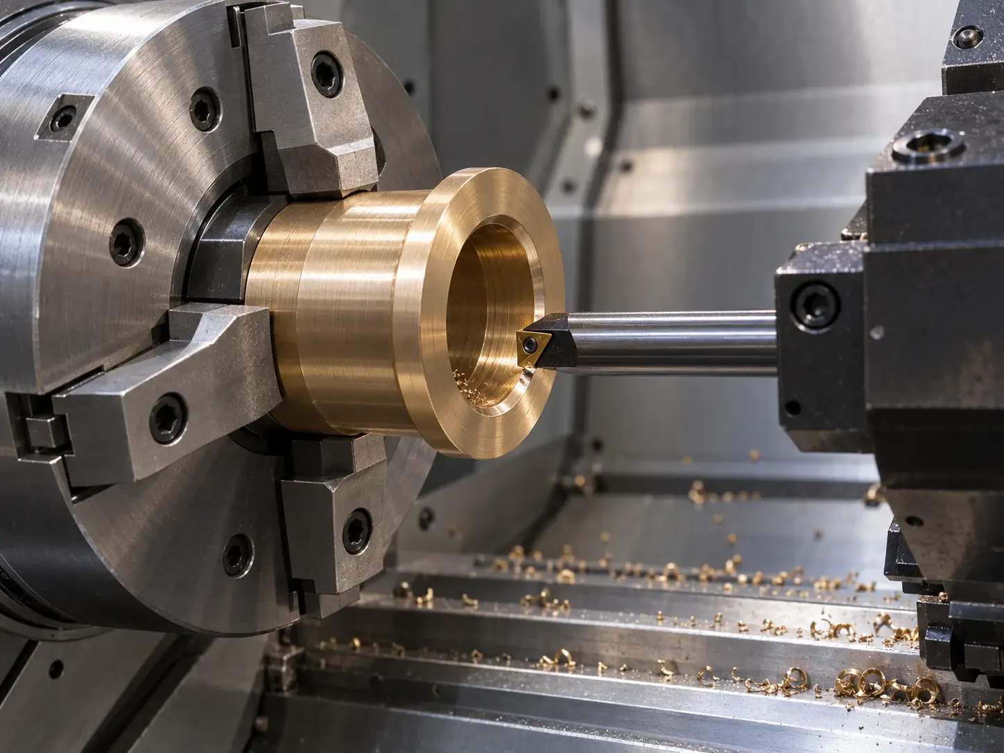
Turning and Bore Finishing
Plan outside diameters, bores, shoulders and end faces together. Review reaming, honing or grinding where the specified finish and geometry require additional operations.
Custom precision bearing bushings made to your drawing. CNC turning and bore finishing for sleeves, flanged bushings and special profiles, with shaft fit, housing fit, material and inspection requirements reviewed before production.
A bearing bushing is a sleeve that provides a sliding surface between a shaft or pivot pin and its supporting housing. Its bore, outside diameter and end faces must work with the mating parts, lubrication method and operating conditions.
CNCPioneer machines custom bushings from specified metal or engineering plastic stock. We review the complete drawing, including wall thickness, flanges, steps, grooves and oil holes, then plan machining and inspection around the dimensions that control assembly and motion.
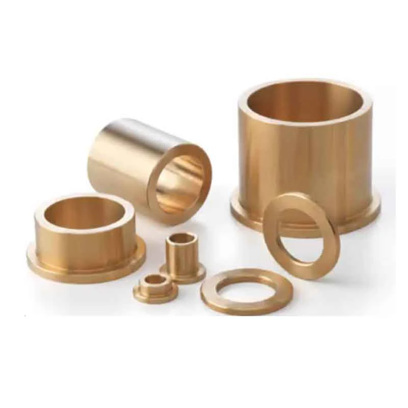
Plan the process around the sliding surface, installation fit and features that locate the bushing in its assembly.
Plan outside diameters, bores, shoulders and end faces together. Review reaming, honing or grinding where the specified finish and geometry require additional operations.
Review stock allowance, clamping and machining sequence to control distortion in slender sleeves. Agree the condition in which final dimensions will be measured.
Machine locating shoulders, lubrication grooves, cross-holes and slots to the supplied design. Coordinate secondary milling or drilling with the turned datums.
Choose tooling and machining allowances for the specified material. Include heat treatment, plating or polymer conditioning in the process review where required.
Check critical bores, outside diameters, lengths and face relationships using the agreed inspection plan. Surface finish and burr condition are reviewed at functional interfaces.
Use drawing revision, material condition and approved inspection criteria to define each order. Quantity, finishing and documentation requirements inform the quotation.
Representative bushing geometries. Material, wall thickness, fit and additional features are specified for your assembly.
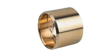
Straight cylindrical sleeves for shaft and pivot interfaces. Specify bore, outside diameter, overall length and entry chamfers, together with the required installation fit.
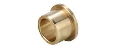
Flanged sleeves with an axial locating face. Define flange diameter and thickness, the mating face and any thrust-surface requirements in addition to the bore fit.
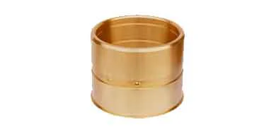
Bushings with specified internal or external grooves. Provide groove position, profile and purpose so lubrication channels and retaining features can be machined correctly.
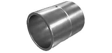
Sleeves with multiple diameters or locating shoulders. Define each mating interface and the datum relationships between the bore, outside diameters and end faces.

Custom sleeves with a drawing-defined slot. Slot width, depth, edge condition and the free-state or installed inspection condition are reviewed before machining.

Bushings with radial holes for a specified lubrication or assembly function. Define hole size and location, and agree deburring requirements at the bore intersection.
Custom bearing bushings for pivoting, rotating and sliding mechanisms across six industries. Match each design to its mating parts, operating environment and maintenance plan.

Bushings for linkage pivots, actuator guides and vehicle production fixtures. Review shaft clearance, retention, lubrication and wear-surface requirements against the assembly drawing.
Explore automotive machining
Sleeves and flanged bushings for gripper pivots, linkage joints and positioning mechanisms. Define compact fits, shaft alignment, permitted play and maintenance access for repeated motion.
Explore robotics machining
Bushings for valve linkages, actuator pivots and equipment guides. Confirm the fluid exposure, temperature, mating material and lubrication method before specifying the bushing grade and finish.
Explore oil & gas machining
Bushings for door mechanisms, service linkages and rail equipment pivots. Review oscillating motion, installation fits, vibration, contamination and replacement access with the equipment drawing.
Explore railroad machining
Custom sleeves and flanged bushings for actuator linkages, pivot assemblies and ground support equipment. Material traceability, functional surfaces and any first-article documentation follow the approved program requirements.
Explore aerospace machining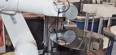
Bushings for equipment linkages and positioning or handling mechanisms. Confirm particle-control needs, lubricant compatibility, material selection and cleaning requirements for the intended location in the machine.
Explore semiconductor machiningMaterials
Specify the exact grade and condition. Review the bushing material together with the shaft, load, motion, temperature and lubrication requirements.
Machined bronze sleeves and flanged profiles to the specified alloy. Confirm the mating shaft, lubrication and material certification requirements.
Custom bushings from the specified aluminum bronze grade. Review material condition, functional surfaces and the service environment with the drawing.
Machined brass sleeves and locating bushings. Confirm that the selected alloy suits the contact load, mating material and wear requirements.
Steel sleeves and bushings with drawing-defined heat treatment where needed. Allow for finishing and dimensional checks after treatment.
Custom stainless sleeves and bushings. Review grade, mating surface, lubrication and any passivation requirements for the intended assembly.
Machined polymer sleeves in specified grades such as POM or PEEK. Confirm material suitability, thermal allowance and the installed fit before production.
Finish selection
Finish selection follows the material and function. Keep the final bore, outside diameter and contact surfaces within the drawing requirements after any treatment.
Define the required surface condition for the sliding bore, mounting diameter and flange face. Avoid a generic finish callout where different surfaces serve different functions.
Review reaming, honing or grinding when appropriate to the geometry and material. Agree stock allowance and inspection after the final operation.
Control bore-entry edges and burrs where grooves or holes intersect a sliding surface. Define any edges that must remain sharp for the assembly.
Review heat treatment against the steel grade and drawing. Plan any required finishing after treatment to meet the final geometry.
Where specified, include passivation and cleaning in the manufacturing route. Confirm the applicable process and the documentation required with the order.
Review coating compatibility, thickness allowance and masking on fitted features. The sliding pair and service conditions determine whether a treatment is suitable.
Machining resources for drawing review, prototypes and repeat-production programs.
Inspection & documentation
Inspection focuses on the dimensions and surface conditions that control installation, clearance and contact with the mating shaft.
Final tolerances, inspection coverage and acceptance criteria are confirmed against your drawing, material and geometry.
Confirm the certificates, inspection reports and production records needed for your order when sharing your drawing.
A bearing bushing provides a sliding interface for a shaft or pivot pin. A bearing housing is the supporting body that locates a bushing or a separate bearing. This page covers custom machined sleeves and bushings.
We review plain sleeves, flanged bushings, stepped profiles, grooves, slots and cross-drilled features against your drawing. The machining route depends on material, wall thickness, feature access and order quantity.
Send the 2D drawing and a 3D model where available, material grade, quantity, surface requirements and delivery needs. Identify bore and outside-diameter fits, mating parts and any inspection or certification requirements.
We machine to the dimensions and limits agreed on the drawing. Review the shaft and housing dimensions together with material and installation conditions. Do not assume that a free-state bore measurement alone defines the final assembled clearance.
Lubrication requirements depend on the material system, mating shaft, load, speed and operating environment. A solid machined metal bushing should not be assumed to be self-lubricating. Identify any specified liner, lubricant inserts or porous bearing material separately so the supply and manufacturing route can be confirmed.
Prototype and repeat-production enquiries are reviewed individually. Material certificates, dimensional reports and customer-specific first-article records can be included in the quotation scope. Price and delivery follow review of the drawing, quantity, material availability, finishing and inspection requirements.
CUSTOM CNC PARTS
Share your drawing, material, quantity and mating shaft or housing requirements. Include critical fits, lubrication features and inspection needs for a manufacturing review and quotation.
 Bronze Bushings
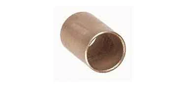 Bronze Sleeve Bushings
 Stainless Steel Bushing