
Datum-Controlled Mounting Features
Mounting faces, locating bores and hole patterns are planned from the drawing datums to control the relationships required at assembly.
CNCPioneer provides CNC machining for aerospace brackets in aluminum, titanium and stainless steel. Send your drawing for a quote on mounting brackets, avionics plates and equipment supports, with material and inspection requirements defined for your order.
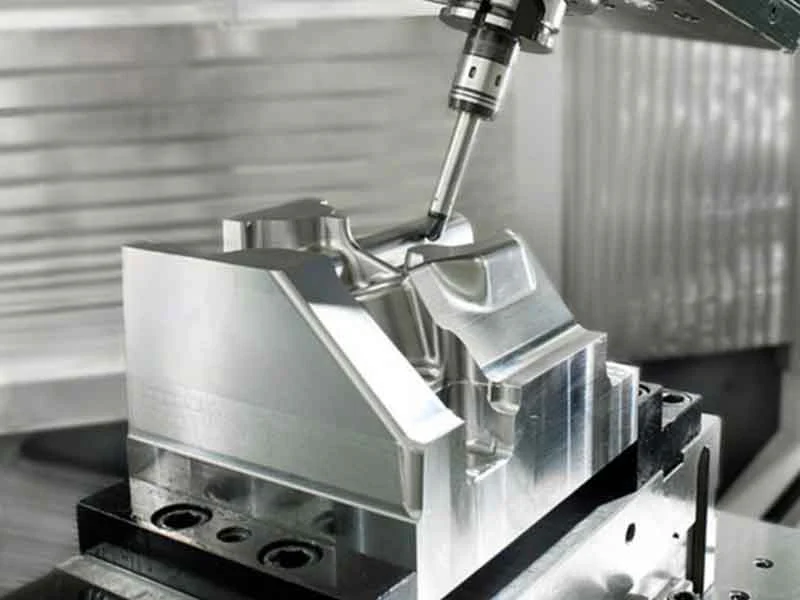
Aerospace brackets connect equipment and structural assemblies through mounting faces, holes, bores and angled interfaces. We machine pocketed supports, mounting plates, blocks and sensor brackets from your component drawing.
Machining is planned around the features that locate the part in the assembly. Hole position, profile, flatness, wall thickness and surface finish are checked against the stated datums and acceptance requirements.
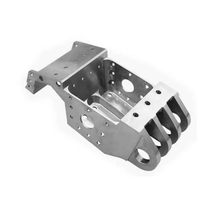
From mounting features to delivery records, the machining and inspection plan follows your bracket drawing.
Mounting faces, locating bores and hole patterns are planned from the drawing datums to control the relationships required at assembly.
Workholding and material removal are planned around lightweight sections and cutter access. Critical geometry is assessed in the specified inspection condition.
Inclined faces, forked supports and intersecting features are reviewed together so the machining sequence addresses their required geometric relationships.
The ordered alloy, material condition and drawing revision form the production record, with certificates and traceability defined for the program.
Coating allowance, masked surfaces, edge breaks and final fit dimensions are addressed before machining, including dimensions specified after treatment.
Material certificates, dimensional reporting and any AS9102 FAIR scope are agreed at quotation and linked to the ordered drawing revision.
Mounting brackets, plates, blocks and supports machined to the material, geometry and acceptance requirements of your program.
Pocketed and ribbed supports with mounting holes, locating faces and forked interfaces, machined around the specified walls, corner radii and datums.

Compact blocks with bores, mounting faces, threaded holes and intersecting features for drawing-defined equipment and structural interfaces.
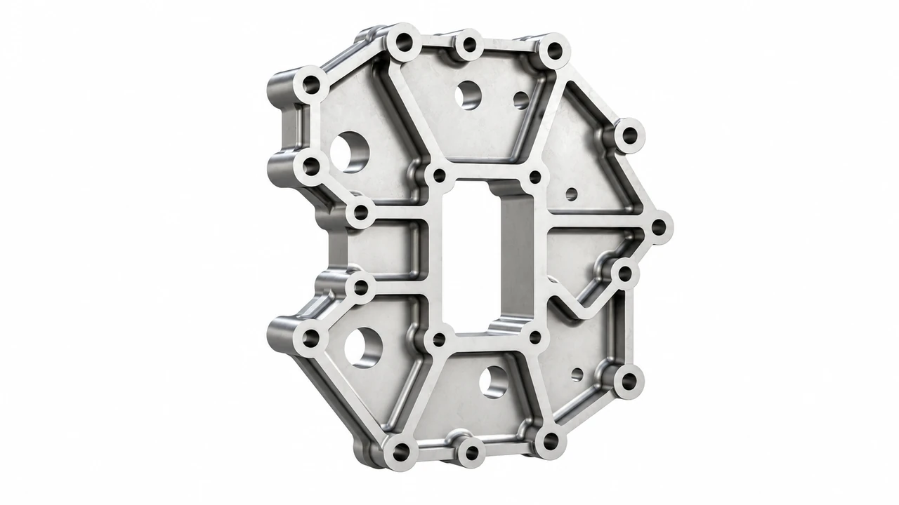
Open frames and contoured brackets with reinforcing ribs, pockets and mounting bosses, produced to the specified material and section geometry.

Equipment plates with mounting-hole patterns, locating features and access openings, including drawing-defined flatness and masked contact areas.
Inclined and gusseted supports for equipment installation, with angled mating faces, weight-relief pockets and drawing-defined attachment features.
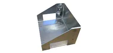
Compact brackets with mounting holes, orientation features and connector clearance for the specified sensor or instrument installation.
Mounting components for aircraft equipment, electric aircraft, space assemblies and UAV systems, with interfaces and documentation defined for each installation.

Equipment mounting brackets and avionics supports with drawing-defined attachment holes, locating faces and treated surfaces for aircraft installations.
Explore aerospace machining
Sensor mounts and equipment brackets with weight-relief pockets, mounting orientation and cable clearance matched to electric-aircraft installations.
Explore eVTOL machining
Payload plates, instrument supports and mechanism brackets with program-defined material records, surface treatment and cleanliness requirements.
Explore satellite machining
Mounting brackets for UAV platforms and associated aerospace equipment, with attachment geometry, environmental finish and delivery records defined by the order.
Explore defense machiningMaterials
Material selection follows your engineering specification. For quotation, include the alloy, product form, temper or heat-treatment condition and required material certificates.
Pocketed brackets and structural supports in the specified temper. Include grain-direction requirements, material certificates and the protective finish with your drawing.
Equipment plates, mounting blocks and supports where corrosion resistance and anodized appearance are relevant. Specify temper, treatment and final mating dimensions.
An aircraft alloy used for its strength and machining characteristics. Specify product form, temper, grain direction and the required corrosion-protection system.
For titanium brackets specified around structural efficiency. Include material condition, minimum sections, edge requirements and the critical features needing inspection.
For stainless mounting components with a specified heat-treatment condition. State that condition so machining, treatment and final inspection can be sequenced correctly.
For corrosion-resistant equipment supports where 316L is specified. Include surface finish, passivation, material records and the dimensions controlling assembly.
Finish selection
Specify the treatment, acceptance criteria and final dimensions on the drawing. Mark surfaces requiring masking, including precision fits, threads and electrical contact areas.
An anodized finish for aluminum brackets, with treated areas, color and thickness defined alongside the final fit requirements.
For drawing-specified hard-coated surfaces, with coating allowance and any post-treatment machining included in the production plan.
A specified conversion treatment for aluminum surfaces. Define the process class and requirements for contact areas or subsequent coatings.
Passivation for the specified stainless grade, with the required cleaning, handling and treatment records included in the order scope.
For contact surfaces requiring the drawing-specified lubricant system. Identify substrate preparation, coating limits and final acceptance checks.
For specified bracket surfaces or fillet zones, with treatment sequence, masked areas and acceptance records defined by the program.
CNC milling and drilling for bracket prototypes and repeat orders. Component envelope, material, wall thickness, angled features and quantity determine the proposed process.
Inspection & documentation
Inspection focuses on mounting datums, hole patterns, wall geometry and final surface condition, with results and delivery records matched to the order.
Dimensional tolerances, geometric requirements, surface finish, treatment acceptance and inspection frequency are confirmed for the specified drawing revision and material.
Confirm the certificates, inspection reports and production records needed for your order when sharing your drawing.
We review mounting brackets, equipment blocks, avionics plates, ribbed frames and sensor mounts for CNC milling and drilling. The drawing and 3D model define the geometry, material and critical assembly interfaces.
Tolerances are confirmed for each drawing, considering component size, alloy, wall thickness, datum access and finishing. Identify critical hole positions, bores, flatness and profile requirements in your enquiry.
These features are assessed for cutter access, workholding and geometric relationships. The proposed machining sequence follows the material, minimum sections and drawing requirements for the individual bracket.
Request AS9102 first-article documentation at quotation. The scope should identify the drawing revision, inspection characteristics, material and process records, results and any customer-specific forms.
Send the 2D drawing and 3D model, material specification, quantity, finish and delivery date. Add critical features and document requirements so CNCPioneer in China can confirm scope, price and schedule.
CUSTOM CNC PARTS
Send your bracket drawing, material, finish and quantity. Add critical features, first-article documents and delivery requirements for a quote matched to your program.
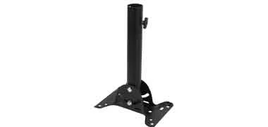 Satellite Bracket Machining
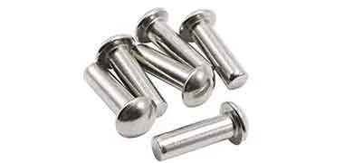 Aerospace Fastener
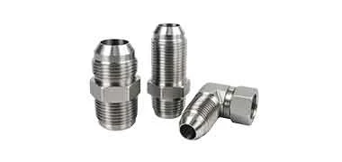 Aerospace Fittings manufacturing
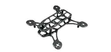 Custom CNC Machined Drone Parts