
Drawing Review for Stator Installation
Review the stator envelope, installation method, locating shoulders and assembly access. Confirm the fit specified by the motor designer before selecting the machining sequence.
Electric motor stator housing machining for custom sleeves, flanged bodies, cooling jackets and end caps. CNCPioneer reviews stator fits, bearing alignment, material, finishing and inspection requirements with your drawing, from prototypes to repeat production.
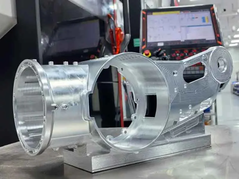
A motor stator housing locates the stator and provides the mechanical interfaces for end caps, mounting features and surrounding equipment. CNC turning, boring and milling produce the cylindrical seats, shoulders, flanges and secondary features defined by the motor assembly drawing.
The machining plan starts with the stator installation method, bearing arrangement and housing material. Bore geometry, wall thickness, cooling features and the final surface condition are reviewed together so the finished part meets the specified assembly requirements.
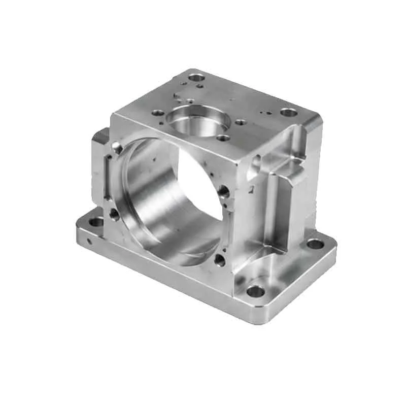
Plan the machining route around the stator seat, bearing arrangement and final assembly condition.
Review the stator envelope, installation method, locating shoulders and assembly access. Confirm the fit specified by the motor designer before selecting the machining sequence.
Treat stator bore diameter, roundness or cylindricity, and roughness as separate drawing requirements. Agree suitable checks for the housing length, material and tolerance.
Plan setups around the relationship between stator seats, bearing pockets, end-cap registers and mounting faces. Locate and inspect each feature from the specified datums.
Assess wall thickness, blank condition, fixturing and material removal sequence for sleeves and lightweight housings. Define the inspection condition for features affected by clamping.
Combine turned bores with milled flanges, cooling passages, ports, connector openings and sensor mounts. Review tool access, edge condition and finishing allowances with the drawing.
Define critical features and the required material, dimensional and finish records at quotation. Carry the approved drawing revision and inspection scope into repeat orders.
Representative configurations for electric motor assemblies. Geometry, material and acceptance requirements follow your component drawing.

Compact sleeves and flanged housings with stator seats, locating shoulders and mounting features for direct-drive and joint actuator assemblies.
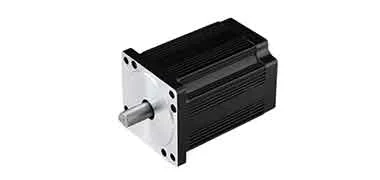
Cylindrical bodies with stator bores, end-cap registers, cable exits and sensor mounting features for brushless motor assemblies.
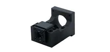
Housings with mounting flanges, bearing interfaces and encoder or connector features. Machine frame dimensions and mating faces to the specified design.

Output-side caps with bearing seats, locating diameters, shaft openings and seal grooves, referenced to the housing and shaft assembly datums.
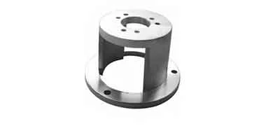
Rear covers with bearing pockets, encoder mounting faces, cable outlets and fastener patterns matched to the motor assembly drawing.
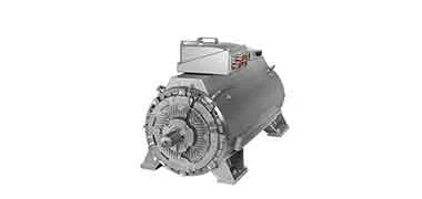
Housing bodies and jackets with machined channels, coolant ports and sealing interfaces. Define channel geometry, closure method and any leak-test requirements with the order.
Stator housings and motor end caps support electric drives across robotics, production machinery, transport and precision equipment. Define the motor interfaces and inspection scope for each application.

Compact stator housings and end caps for shoulder, elbow, hip and knee actuators, with joint mounting features, bearing interfaces and cable routing defined by the assembly.
Explore humanoid robot machining
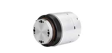
Servo and torque motor housings for robots, cobots and automated machinery. Review stator seats, end-cap registers, mounting flanges and cooling features for the drive assembly.
Explore robotics machining
Motor housings for surgical robots, rehabilitation devices and positioning equipment, with compact bearing arrangements, specified materials and assembly-specific surface requirements.
Explore medical machining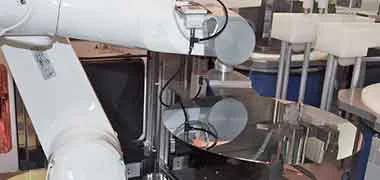
Stator housings and end caps for wafer-handling drives and positioning stages. Specify bore alignment, mounting datums, cable routing and equipment cleanliness requirements.
Explore semiconductor machining
Custom motor housings for electric-drive development, test equipment and production machinery. Review stator fits, cooling interfaces, sealing features and inspection requirements with the drawing.
Explore automotive machining
Housings and end caps for electric actuators and aerospace production equipment, with weight, bearing alignment, mounting interfaces and material traceability defined for the program.
Explore aerospace machiningMaterials
Aluminum is a common starting point for stator housings. Select the exact alloy and condition around weight, heat transfer, stiffness, operating temperature and the specified installation method.
For machined housing bodies, flanges and end caps. Review wall thickness, bore requirements and the final anodized or coated condition with the drawing.
For housings machined from specified extruded profiles or tube. Confirm the starting section, temper and machining stock on the stator seat and mounting faces.
An option where the design specifies higher-strength aluminum. Check finish compatibility, component loads and the required material condition before production.
A drawing-specific option for weight-sensitive or demanding service conditions. Review machining access, thermal requirements and the mating materials for the assembly.
For steel housing and end-cap designs requiring the specified strength or stiffness. Agree heat treatment, corrosion protection and the condition in which fits are measured.
For stainless housings and end caps specified for corrosive or cleanable environments. Review weight, thermal requirements and the finish of locating surfaces.
For strength-focused stainless components. Specify the heat-treatment condition and final dimensional requirements for bearing and mounting interfaces.
For drawing-specified insulating inserts, bushings or spacers used with a metal motor housing. Define the grade, mating fits and service temperature for each accessory.
Finish selection
Identify stator seats, bearing bores, sealing surfaces and electrical contact areas before selecting a finish. Specify masking, coating allowance and the condition for final dimensional inspection.
A finish option for aluminum housings and end caps. Define treated areas and any bore or grounding surfaces that must remain uncoated.
Consider for aluminum surfaces with a specified wear requirement. Include coating growth and any post-treatment machining in the dimensional plan.
Review the passivation method against the stainless grade and service environment. Agree cleaning, handling and documentation requirements with the order.
A plating option where specified for the housing material and operating conditions. Identify bearing seats and stator interfaces that need masking or machining allowance.
For specified exterior color and surface protection. Mask precision fits, threads, coolant connections and required electrical contact areas.
A specialist option for selected end-cap contact surfaces. Confirm the substrate, coating process and functional requirement before including it in the machining route.
Turning, boring and milling for motor housing prototypes and repeat orders. Housing diameter, length, wall thickness, cooling features and quantity determine the proposed process.
Inspection & documentation
Inspect the stator seat and its relationship to bearing bores, end-cap registers and mounting datums. Define checks and delivery records for the final finished condition.
Bore limits, geometric tolerances, surface roughness, coating allowances, inspection frequency and any cooling-jacket leak testing are agreed for the specific drawing and order.
Confirm the certificates, inspection reports and production records needed for your order when sharing your drawing.
The range includes frameless torque motor sleeves, BLDC housing bodies, servo and stepper housings, cooling jackets and matching end caps. Send the component drawing so we can review the envelope, features, material and machining route.
State the stator installation method, bore limits, surface requirements and assembly datums on the drawing. Fits for bonding, shrink fitting or clamping must follow the motor designer's requirements. Specify the required geometric relationships between the stator seat, bearing bores and mounting faces.
Cooling fins, jacket channels, coolant ports and seal grooves can be reviewed with the housing design. Share channel geometry, minimum walls, closure details and connection interfaces. Any assembly, cleaning or leak testing must be defined and agreed with the order.
Identify treated and masked areas, coating thickness and the final bore or register limits. The agreed inspection pack can include material certificates, dimensional results and finish records, with bore form, alignment or roughness checks where specified.
Send a 2D drawing and 3D model, material grade and condition, housing quantity, stator and bearing fit requirements, finish and requested delivery date. CNCPioneer in China will review the machining and inspection scope before confirming price and lead time.
CUSTOM CNC PARTS
Send your housing drawing or 3D model, material, stator installation method, bearing fits, finish and quantity. Include cooling features and required inspection records for a machining review and quote.
 Humanoid Robot Joint Housings
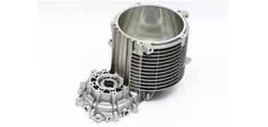 Motor Housing Machining
 Robot Actuator Housings
 Battery Housing Manufacturing