
Impact-Load Structural Analysis DFM
Every eVTOL landing gear primary structural component must be designed for the dynamic design landing load.
Custom CNC Machining For Precision Actuator Parts made to your drawing. Review journal diameters, runout and drive interfaces, material, finishing and inspection requirements before production.

eVTOL landing gear and actuator components represent two distinct but structurally related product families unified by one critical design requirement: the combination of high structural load capacity and minimum mass.

Coordinate geometry, material, finishing and inspection around the part's intended function.
Every eVTOL landing gear primary structural component must be designed for the dynamic design landing load.
The performance of every dynamic seal in eVTOL actuator systems is governed by piston rod surface finish.
The housing bore accuracy (±0.003mm) governs whether the ball screw nut is correctly centered for designed running clearance.
All primary structural eVTOL landing gear components are life-limited primary structural parts under proposed FAA AC 21.17-1.
Review journal diameters, runout and drive interfaces and functional requirements before defining the process.
Review geometry, batch quantity and process requirements to prepare the quotation.
Explore representative configurations and share your drawing for a product-specific review.
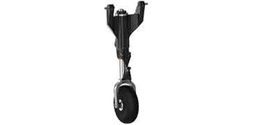
Shock Absorber Strut Body & Piston Rod machined to your drawing. Confirm material, functional dimensions and finish before production.

Skid attachment bracket: lug bore ±0.005mm H8; lug pair coaxiality ±0.005mm; skid tube clamp bore ±0.200mm; clamp bolt holes ±0.010mm true position; TC4 AMS 6931 STA at landing load-governed cross-sections; AMS 2430 shot peen; mass ±2g.
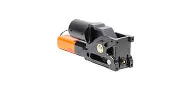
Gear pivot trunnion structural body: pivot bore ±0.002mm; upper structural lug pair ±0.005mm; actuator hard-point ±0.010mm; drag brace attachment lug ±0.005mm; 5-axis compound face angles ±0.020°; TC4 AMS 6931 STA; shot peen.
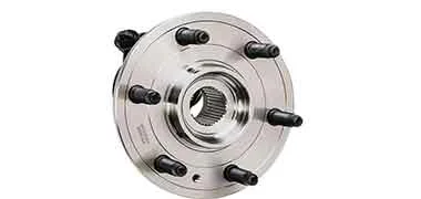
Wheel axle: outboard/inboard bearing seats ±0.002mm k5; concentricity ±0.002mm single-setup; brake disc flange face perpendicularity 0.010mm; thread ±0.005mm pitch diameter.

EMA cylinder housing: ball screw nut engagement bore ±0.003mm H7; roundness ±0.002mm; output rod guide bore ±0.003mm; motor interface flange ±0.005mm; mounting trunnion/clevis bore pair coaxiality ±0.005mm; angular alignment ±0.020°.
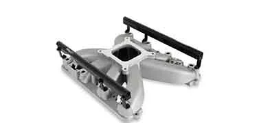
EHA Manifold & Retraction Actuator Components machined to your drawing. Confirm material, functional dimensions and finish before production.
Match the component to its operating environment, assembly interfaces and documentation requirements.

Precision piston rods, actuator housings, clevises and pivot fittings for aircraft landing gear and motion systems. Material, surface finish and inspection requirements are confirmed with your drawing.
Explore aerospace machining
Actuator housings, drive shafts, bearing seats and mounting interfaces for robot joints and automation equipment. Review concentricity, fit and assembly alignment with your drawing.
Explore robotics machining
Precision shafts, piston rods, cylinder bodies and mounting components for automotive actuation systems. Material, finish and production inspection are agreed for each application.
Explore automotive machiningMaterials
Confirm the exact grade, delivery condition and finish compatibility with your drawing.
UTS: 1,480 MPa; Yield: ~1,380 MPa; Density: 7.85 g/cm³; Fatigue: 700 MPa true endurance limit.
UTS: 1,800 MPa; Yield: ~1,650 MPa; Density: 7.85 g/cm³; Fatigue: 800 MPa.
UTS: 1,100 MPa; Yield: 1,000 MPa; Density: 4.43 g/cm³; Fatigue: 650 MPa; K_IC ≥ 55 MPa·√m.
UTS: 950 MPa; Yield: 880 MPa; Density: 4.43 g/cm³; Fatigue: 600 MPa.
UTS: 572 MPa; Yield: 503 MPa; Density: 2.80 g/cm³; Fatigue: ~160 MPa at 10⁸.
UTS: 470 MPa; Yield: 324 MPa; Density: 2.78 g/cm³; Fatigue: ~138 MPa; K_IC ≈ 33 MPa·√m.
UTS: 1,310 MPa; Yield: 1,170 MPa; HRC 44–47; Density: 7.78 g/cm³; Fatigue: 620 MPa.
UTS: 485 MPa; Yield: ~170 MPa; Density: 7.99 g/cm³; Fatigue: 210 MPa.
Finish selection
Select the finish around the specified material, functional surfaces and service conditions. Confirm process details and acceptance requirements with your drawing.
Review hard chrome against the material, functional surfaces and intended service conditions.
Review electroless ni-p against the material, functional surfaces and intended service conditions.
Review dlc coating against the material, functional surfaces and intended service conditions.
For 7075-T6 EMA housing bodies, wheel hub bodies, and secondary gear structural fittings: HV 400+ wear resistance; corrosion protection in gear bay environment.
Review shot peen against the material, functional surfaces and intended service conditions.
All 17-4PH H900 uplock/downlock bodies, actuator clevises, and metering pins — passivation restores passive oxide layer at all machined surfaces; prevents flash rusting in gear bay humidity environment.
Machining resources for drawing review, prototypes and repeat-production programs.
Inspection & documentation
Review material identity, machining datums, functional dimensions and production records for your component.
Final tolerances, inspection coverage and acceptance criteria are confirmed against your drawing, material and geometry.
Confirm the certificates, inspection reports and production records needed for your order when sharing your drawing.
The product range includes Shock Absorber Strut Body & Piston Rod, Skid Gear Structural Fittings & Brackets, Retractable Gear Structural Components. Custom geometry is reviewed against the approved drawing.
Material options include 4340 Steel QT HRC 40, 4340 Steel QT HRC 52, TC4 Ti-6Al-4V AMS 6931 STA. The exact grade and condition should be confirmed for your application.
Define journal diameters, runout and drive interfaces, together with datums, tolerances and required surface condition.
Finishing options include hard chrome, electroless ni-p, dlc coating. Applicability is reviewed against the specified material and geometry.
Pricing and delivery are confirmed after reviewing the drawing, material availability, quantity, machining route, finishing and inspection scope.
CUSTOM CNC PARTS
Share your drawing or 3D model, material, critical dimensions, finish and order quantity. We’ll review the machining route, inspection scope and delivery requirements.
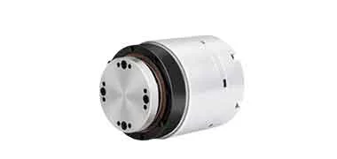 Robot Actuator Housings
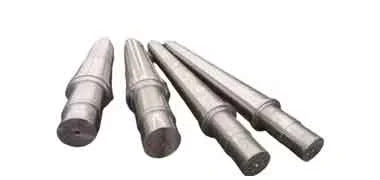 Aerospace Precision Shafts for Flight-Critical Rotating Systems
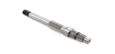 Aluminum Shafts CNC Turning
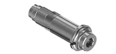 Motor Shaft Machining