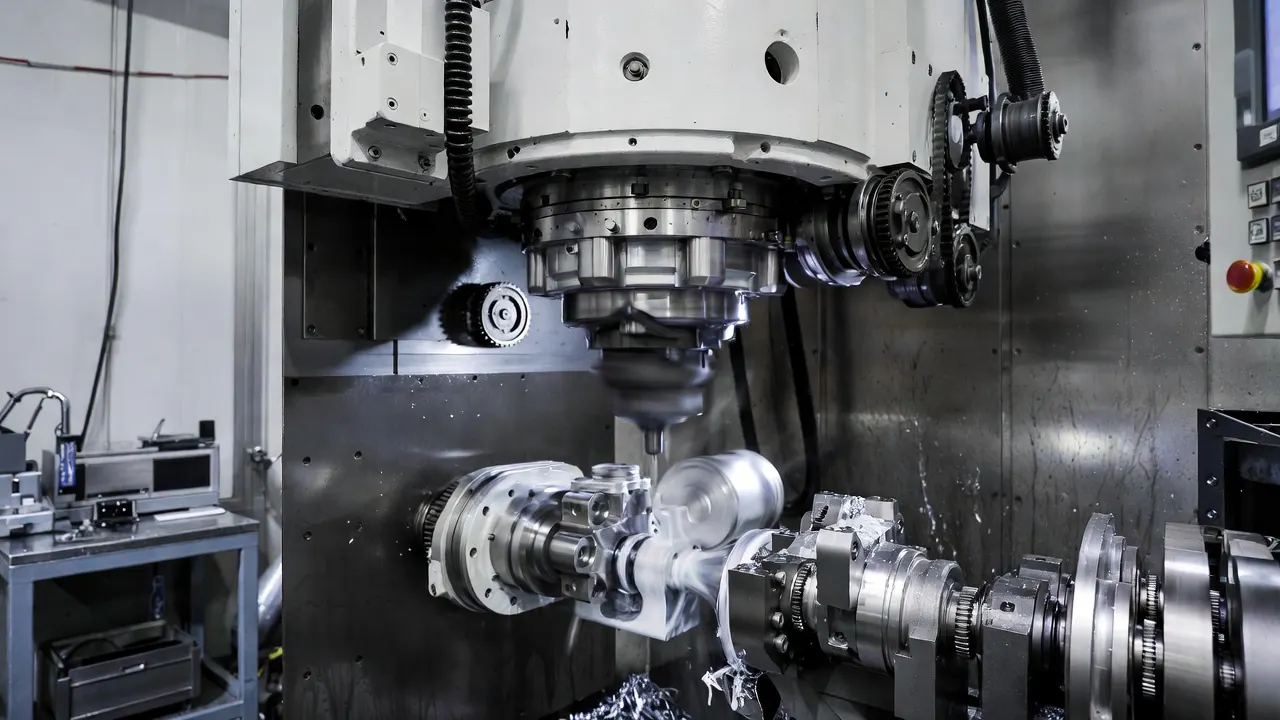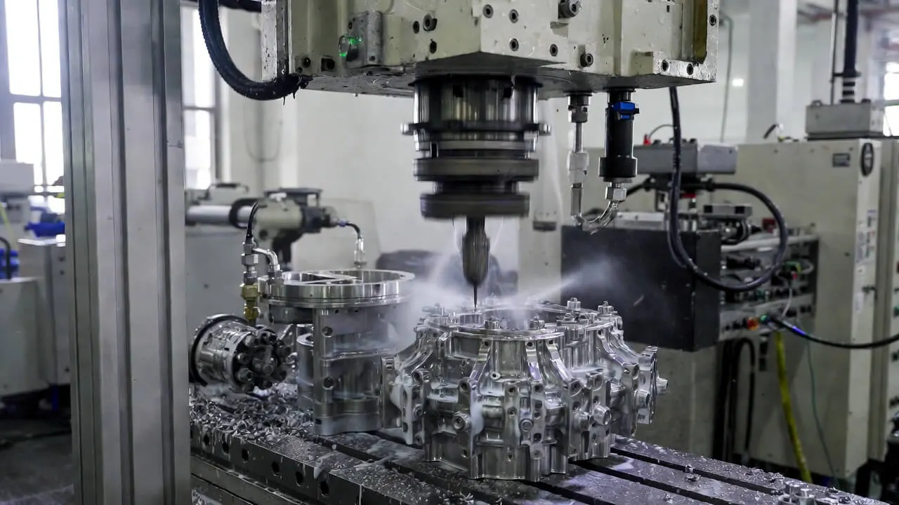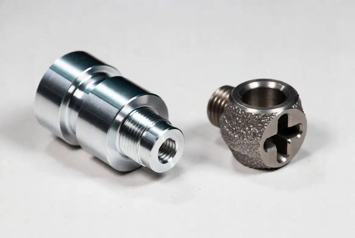
A CNC lathe primarily turns the workpiece; a CNC mill primarily rotates the cutter. This difference explains why turning is a natural starting point for many round parts and milling for pockets, faces, and other accessible non-round features.
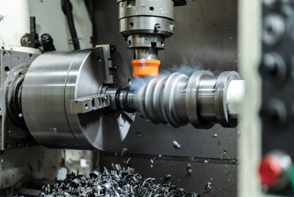
The terms “lathe versus mill” and “turning versus milling” are often used for the same process-selection question. Modern machines can combine both capabilities, so select a manufacturing route from the part's features instead of assuming a machine label defines every operation it can perform.
The Core Process Difference
In turning, the rotating workpiece provides the main cutting motion. Tools move relative to it to form diameters, faces, tapers, grooves, and threads. Turning centers may include driven tooling, additional axes, or subspindles for other operations.
In milling, a rotating cutter removes material while the machine controls the relative position of tool and workpiece. A mill can generate planar faces, pockets, slots, hole patterns, and contours. Additional axes can improve access or permit more complex tool orientations.
For equipment details, see CNC lathe types and operation. For process fundamentals, use the dedicated turning and milling guides.
CNC Turning vs Milling: Feature-Based Comparison
| Feature or concern | Turning | Milling |
|---|---|---|
| Coaxial diameters and shoulders | Often efficient to produce around the spindle axis | Possible for some geometries, but may add operations |
| Pockets and planar faces | May need driven tools or a second process | Common applications when access is available |
| Long, slender features | Support and deflection control are important | Workholding and cutting-force direction need review |
| Multi-face detail | Depends on the turning center's additional capabilities | May use indexing or multi-axis setups |
| Stock form | Frequently bar, round blanks, castings, or forgings | Frequently plate, block, castings, or other blanks |
| Cost driver | Setups, cycle, tooling, support, and quantity | Setups, access, stock removal, tooling, and quantity |
When to Start with Turning
Shafts, bushings, spacers, pins, and many threaded fittings have rotational features that suit turning. A single setup may establish related diameters and shoulders without repeatedly relocating the part. This can simplify the manufacturing route when the geometry and stock are suitable.
Review long overhangs, thin walls, interrupted cuts, and small features before choosing tooling and supports. A round part with transverse holes or flats may need driven-tool operations or a milling setup. For small slender components, Swiss machining may be another route to evaluate.
When to Start with Milling
Housings, brackets, plates, fixtures, and molds often need pockets, hole patterns, faces, and contours. Milling can create these where the cutter and holder can reach and the workpiece can be supported. Internal corner radii and tool length should be reviewed early.
Multiple faces do not automatically require simultaneous five-axis machining. Depending on the geometry, indexed setups or a simpler machine may be sufficient. Compare the number of setups, datum transfer, programming effort, and inspection access rather than choosing by axis count alone.
When a Part Needs Both: Mill-Turn Machining
A mill-turn center combines turning with driven-tool or milling functions. It can reduce transfers for suitable parts that need round geometry plus holes, flats, slots, or other features. Fewer transfers can help control relationships between features and reduce handling.
That benefit is not universal. Machine availability, tooling access, programming, workholding, and cycle time still matter. A two-machine route can be appropriate when it is well controlled and more economical. Ask how the supplier will maintain datums and inspect relationships between operations.
Materials, Accuracy, and Cost
Many metals and engineering plastics can be turned or milled. The relevant questions are exact grade and condition, stock availability, heat and chip behavior, workholding, and the geometry to be produced. See the CNC materials selection guide for the common material families.
Neither process has one universal tolerance. Feature size, material, machine condition, tooling, setup, and measurement all influence capability. Specify the functional dimensions and relationships, then obtain confirmation for the actual part.
For cost, compare stock, programming, setups, cutting, secondary processing, inspection, and handling. An apparently faster cutting method can lose its advantage if it needs several extra transfers. Conversely, a sophisticated mill-turn setup may not pay off for a simple one-off component.
Three Illustrative Selection Examples
- A stepped shaft with threads: start by evaluating turning; review support and the relationship between its diameters.
- A rectangular housing with pockets and a mounting-hole pattern: start by evaluating milling; review wall stiffness, tool reach, and datums.
- A cylindrical fitting with cross-holes and wrench flats: compare a mill-turn route with turning followed by a controlled milling setup.
These are geometry examples, not price or delivery promises. The drawing may introduce requirements that change the preferred route.
Prepare the Project for Review
Provide the model, drawing, material, quantity, finish, and critical features. Identify which dimensions must relate to one another and whether the order is a prototype or repeat production. The supplier can then propose the setups, machining route, and inspection plan.
Explore CNC turning and milling services or submit your drawing to review the practical options for the part.
For a component example, review the drawing requirements for custom motor shafts.