
Review the Mating Interfaces
Check the flange against its shaft, housing or equipment interface. Identify the locating features, fastener pattern and assembly clearances before selecting the machining route.
CNCPioneer machines custom aluminum flanges for mounting, connecting and sealing interfaces. Send your drawing to review the alloy, locating bores, bolt pattern, face requirements and finish for prototypes or repeat production in China.
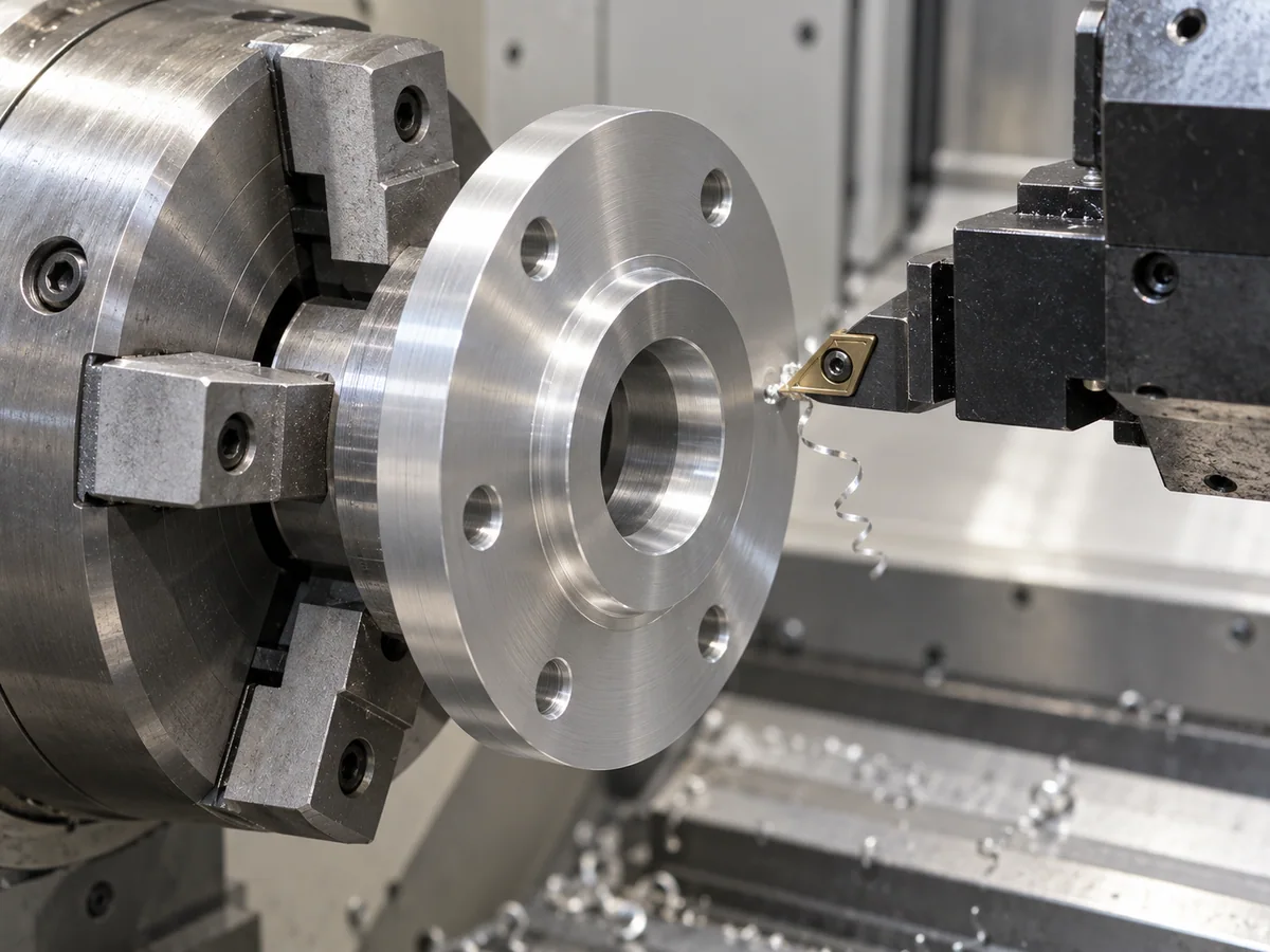
An aluminum CNC machining flange provides a bolted connection between a shaft, housing, pipe or equipment assembly. Turning and milling produce the locating diameter, central bore, mounting face, bolt pattern and any drawing-defined sealing features.
The machining plan follows the mating components and intended service. Define the alloy and temper, critical fits, face requirements and final surface treatment together so the flange can be inspected in its specified delivery condition.
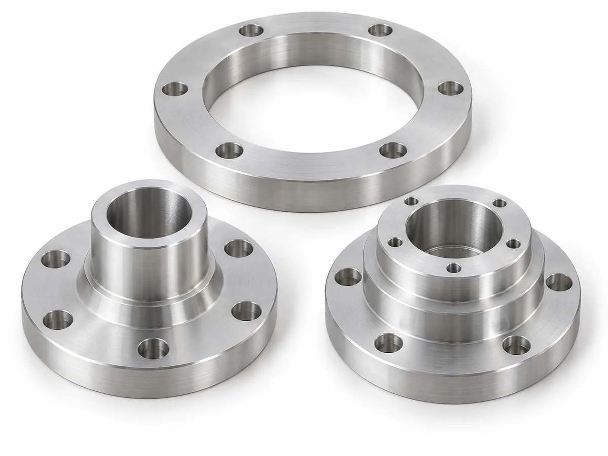
Coordinate aluminum stock, machining datums, functional interfaces and finishing around your flange drawing.
Check the flange against its shaft, housing or equipment interface. Identify the locating features, fastener pattern and assembly clearances before selecting the machining route.
Coordinate facing, boring and outside-diameter turning with drilling, tapping and secondary milling. Plan setups around the relationships between the bore, register and mounting face.
Review stock condition, wall thickness, workholding and material removal for thin flanges. Agree the measurement condition for features affected by clamping or part support.
For sealing flanges, review the mating seal, face roughness, flatness and any groove. Keep sealing requirements distinct from cosmetic or non-functional surface requirements.
Identify coated and masked areas before machining. Review finishing allowances on bores, threads and registers, and define which dimensions must be accepted after treatment.
Carry the approved drawing revision, material specification, inspection plan and finish requirements into repeat orders. Confirm requested material, dimensional and treatment records at quotation.
Representative flange configurations. Material, dimensions and acceptance requirements follow your approved drawing.

Flanges with locating bores, raised registers and bolt patterns for equipment mounting. Define the mating face, fastener layout and assembly datums.
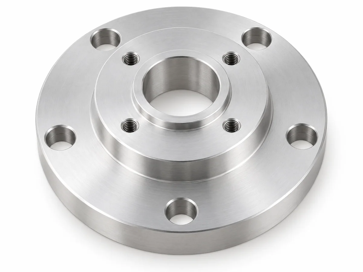
Stepped flange adapters joining different interfaces. Review the registers, face-to-face distance, hole patterns and access required on each side of the connection.

Hub-and-flange parts with extended bores, shoulders or keyways for shaft interfaces. Specify the fit, locating diameter and drawing-defined geometric relationships.

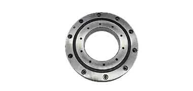
Annular flanges and spacer rings with machined faces, bores and shoulders. Review section thickness, workholding and the required final flatness or parallelism.

Lightweight mounting interfaces for robot tooling, joints and actuators. Machine locating registers, fastener patterns and relief features to the specified assembly drawing.

Flanged components with threaded bores or necks for drawing-defined connections. Confirm thread form, engagement, seating face and any sealing requirements before production.
Aluminum flanges connect equipment through locating, mounting and sealing features. Select the material and inspection scope for the actual assembly and operating environment.

Mounting flanges and flanged hubs for robot tooling, actuator housings and automated fixtures, with locating registers and bolt patterns matched to the assembly.
Robotics machining
Aluminum flange adapters for electric-drive development, test rigs and production equipment. Define shaft or housing interfaces, material condition and finished-part inspection requirements.
Automotive machining
Flanges for aerospace equipment mounts, actuator interfaces and ground-support assemblies, with drawing-defined geometry, specified alloy and order-specific material and inspection records.
Aerospace machining
Flange rings, equipment interfaces and access connections for semiconductor machinery. Specify mounting datums, sealing geometry, permitted finishes and cleanliness requirements for the equipment.
Semiconductor machining
Mounting flanges and connection plates for medical equipment, positioning units and instrument assemblies, with edge condition, finish and material traceability defined by the order.
Medical machining
Aluminum mounting and adapter flanges for instrument enclosures and electronic equipment. Review housing fits, connector clearances, surface treatment and any required electrical contact areas.
Electronics machiningMaterials
Specify the exact alloy, temper and starting form. Selection follows the flange design, mating materials, service conditions and required finish.
A common option for machined mounting and adapter flanges. Confirm the stock form, delivery condition and final requirements for fits, faces and treatment.
An option for drawing-specified structural and equipment flanges. Review the required material standard, available stock section and surface finish with the quotation.
For designs specifying higher-strength aluminum. Confirm the material condition, service environment and finish compatibility rather than substituting alloys without drawing approval.
Finish selection
Choose the finish around corrosion protection, appearance and functional surfaces. Identify any bores, threads, registers or seal faces that need masking.
Retain the machined surface with specified burr removal and edge breaks. Protect sealing faces and locating features during handling.
Prepare permitted surfaces for a uniform matte appearance. Define protected fits, threads and seal faces before blasting.
Clear or colored anodizing to the agreed finish specification. Review dimensional allowance and contact areas before machining.
A hard anodic coating where specified by the design. Account for coating effects on bores, registers and threaded features.
Review conversion coating against the alloy and service requirements. State electrical contact, paint compatibility and masking needs on the drawing.
A plated finish subject to alloy and process review. Agree preparation, coating allowance and inspection requirements for functional flange surfaces.
CNC turning, facing, boring and milling for aluminum flange prototypes and repeat orders. Diameter, thickness, geometry, stock form and quantity determine the proposed machining route.
Inspection & documentation
Inspect the flange from its assembly datums, with particular attention to locating fits, hole patterns, mating faces and the final treated condition.
Tolerances, inspection frequency, surface roughness, coating acceptance and any pressure or leak testing are defined and agreed for the individual drawing and order.
Confirm the certificates, inspection reports and production records needed for your order when sharing your drawing.
We review mounting flanges, adapters, flanged hubs, rings, robot interfaces and threaded configurations from customer drawings. The component envelope, wall thickness, features and material condition determine the machining route.
6061, 6082 and 7075 can be reviewed in the specified temper and stock form. Selection must follow the design loads, operating environment, mating materials and surface treatment. Use the alloy required by the approved drawing; substitutions need customer approval.
Capability is reviewed for the flange size, alloy, geometry, fixturing and finishing route. Specify the critical bore and register fits, hole positions, face geometry, groove dimensions and roughness on the drawing. Define whether acceptance dimensions apply before or after coating.
Anodizing changes the surface dimensions, with the effect depending on the process, alloy and preparation. Identify the final fit limits, coating thickness and masked areas before machining. Specify any protected seal faces, electrical contact areas or threaded features.
Send the 2D drawing and 3D model, aluminum grade and temper, quantity, required finish and delivery date. Mark the critical fits, face requirements and inspection documents. CNCPioneer in China will review the scope before confirming the quote and schedule.
CUSTOM CNC PARTS
Share your flange drawing, alloy and temper, mating fits, face requirements, finish and quantity. Include the inspection documents needed for a drawing-specific machining review and quote.
 CNC Machined Flanges
 Aluminum CNC Turning Parts
 Electric Motor Stator Housing Machining
 CNC Turning Bearing Housings