
Review the Complete Interface
Use your 2D drawing and 3D model to identify the locating faces, hole pattern, mating features and assembly clearances. Include the connected components when their geometry affects the machining plan.
Custom aluminum connector bodies, mounting interfaces and adapter parts machined to your drawing. CNCPioneer in China reviews the alloy, hole positions, threads, mating faces and finish for prototypes and repeat orders. Send your design to request quotes.
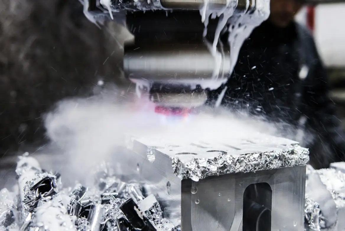
An aluminum CNC milling connector joins, locates or mounts components within an assembly. Its design may combine machined pockets, bores, threaded holes, locating faces and mounting features in one part. The mating components determine which dimensions and surfaces need the closest control.
We review the connection as an assembly interface: how it locates, how fasteners are accessed and which surfaces must remain clear after finishing. Share the mating-part details and intended operating conditions so the machining and inspection plan addresses the features that matter.
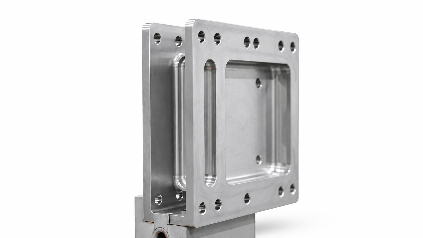
Coordinate the design, material and finish before production so the connector can be checked against its assembly requirements.
Use your 2D drawing and 3D model to identify the locating faces, hole pattern, mating features and assembly clearances. Include the connected components when their geometry affects the machining plan.
Review pockets, internal corners, cross-holes and threaded features for tool access. Features on several faces may require additional setups, with datums carried through the machining sequence.
Confirm the aluminum alloy, temper and starting form before quotation. Stock size, wall thickness and the amount of material removed guide workholding and process planning.
Specify the coating, appearance and protected areas before machining. Include final fit limits for treated bores and threads, plus any surfaces that must remain uncoated.
Focus inspection on the dimensions that locate and secure the connection. Agree suitable checks for hole positions, bores, threads, mating faces and edge condition.
Keep the drawing revision, alloy specification, finish and inspection scope consistent between orders. Quantity and delivery requirements are reviewed for each quotation.
Representative configurations for drawing review. The final geometry, material and machining route follow your approved design.

Housings with internal cavities, mounting holes and locating surfaces. Specify the insert envelope, wall sections and clearance needed for assembly.
Connection bodies combining threaded openings, machined faces and mounting features. Confirm thread details, port positions and any drawing-defined sealing requirements.

Machined interfaces for equipment housings and connector mounts. Review bolt patterns, locating features, recesses and access to the connected assembly.
Aluminum connector bodies and interfaces can be reviewed for the following equipment applications. The drawing defines the function, service conditions and acceptance requirements.

Mounting connectors, adapter interfaces and connection blocks for tooling and automation equipment. Define assembly datums, fastener access and the required mounting geometry.
Explore robotics machining
Connector housings and mounting interfaces for instruments and electronic enclosures. Specify insert clearances, protected contact surfaces and the required finish.
Explore electronics machining
Aluminum connection hardware for test equipment, fixtures and vehicle-related assemblies. Review the interface dimensions, operating environment and order-specific inspection scope.
Explore automotive machining
Connector mounts and adapter components for machine frames and equipment housings. Define cleanliness, permitted finishes and any specific sealing or handling requirements.
Explore semiconductor machining
Connection parts for instrument mounts, positioning equipment and medical-device housings. Material, edge condition, finish and documentation follow the equipment drawing.
Explore medical machining
Machined connector interfaces for equipment mounts and ground-support assemblies. Specify the approved alloy, mating dimensions and required material and inspection records.
Explore aerospace machiningMaterials
Use the alloy and temper required by your design. Stock availability, finish requirements and the intended service are reviewed before quotation.
An option for drawing-specified connector bodies and mounting interfaces. Confirm the stock form, condition, fit requirements and final surface treatment.
For designs specifying 6082 aluminum. Include the material standard, available section size and required records when requesting a quote.
For designs specifying 7075 aluminum. Review the required temper, service conditions and finish compatibility; material substitutions need drawing approval.
Finish selection
Define appearance and functional surface requirements together. Specify masking and final dimensions for bores, threads, contact faces and mounting features.
Retain the machined surface with specified burr removal. Identify edges and mating faces that require particular attention during handling and inspection.
Review permitted surfaces for blasting. Protect critical bores, threads and mating faces as required by the drawing and approved finish specification.
Confirm the anodizing specification and final fit requirements before machining. Identify surfaces that must remain uncoated, including any required electrical contact areas.
Review the coating against the selected alloy and equipment requirements. Agree treatment coverage, protected surfaces and the records needed with delivery.
CNC milling, drilling, boring and tapping for connector bodies and mounting interfaces. Part size, feature access, stock condition and quantity determine the proposed setup and production schedule.
Inspection & documentation
Check the connector from its assembly datums and assess the finished condition of the features that locate, fasten or mate with other components.
Tolerances, inspection coverage and finishing acceptance are agreed for the individual drawing. Any sealing, electrical or other functional testing requires a defined procedure and acceptance criteria.
Confirm the certificates, inspection reports and production records needed for your order when sharing your drawing.
We review connector bodies, housings, mounting interfaces and adapter parts from customer drawings. Pockets, bores, threads and mounting holes are assessed for access, workholding and inspection. Send the mating-part details if they affect the connection.
Use the alloy and temper required by your approved design. 6061, 6082 and 7075 can be reviewed with the specified stock form, service conditions and surface treatment. Availability and any proposed substitution are confirmed during quotation.
Achievable tolerances depend on the geometry, alloy, wall sections, workholding and finish. Mark the critical hole positions, bores, threads and mating faces on your drawing. We review the machining and measurement approach before confirming those requirements.
Anodizing can be reviewed as part of the manufacturing scope. Specify the process, coating thickness, color and masked areas. Final fit limits and any protected contact surfaces should be agreed before machining.
Prototype and repeat-production enquiries are reviewed individually. Order quantity, material availability, setup requirements, finishing and inspection determine the quoted minimum quantity and schedule. Share your target delivery date and expected repeat volume for review.
Send CNCPioneer in China your 2D drawing and 3D model, alloy and temper, order quantity, finish and target delivery date. Highlight critical fits, mounting features and inspection records. We review the scope before confirming pricing and production timing.
CUSTOM CNC PARTS
Share your connector drawing, aluminum grade, quantity and finish. Include the mating interfaces, critical dimensions and inspection requirements for a project-specific review from CNCPioneer in China.
 Electrical Connector
 Aluminum CNC Turning Parts
 Aluminum CNC Machining Flange
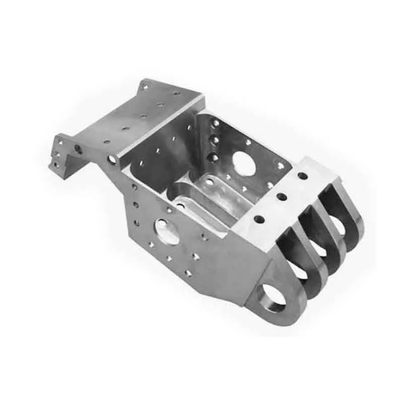 CNC Machining For Aerospace Brackets