
Custom EV Charging
Connector Manufacturing
CNCPioneer is an IATF 16949 and AS9100D certified custom EV charging connector manufacturing specialist delivering vehicle-side inlet housing bodies (Type 2/CCS2/CCS1/NACS/GB-T), industrial AGV docking contacts, battery swap HV connector arrays, electric bus pantograph contact shoes, marine shore power connector bodies, and custom proprietary connector designs — with vehicle inlet socket bore ±0.010mm, electromagnetic lock receiver bore ±0.005mm, AGV docking contact OD ±0.002mm, and battery swap ta-C DLC 3.0μm at 365,000-cycle specification on 78+ Swiss CNC lathes and 66+ MAZAK mill-turn centers since 2011.
What Is Custom EV Charging
Connector Manufacturing?
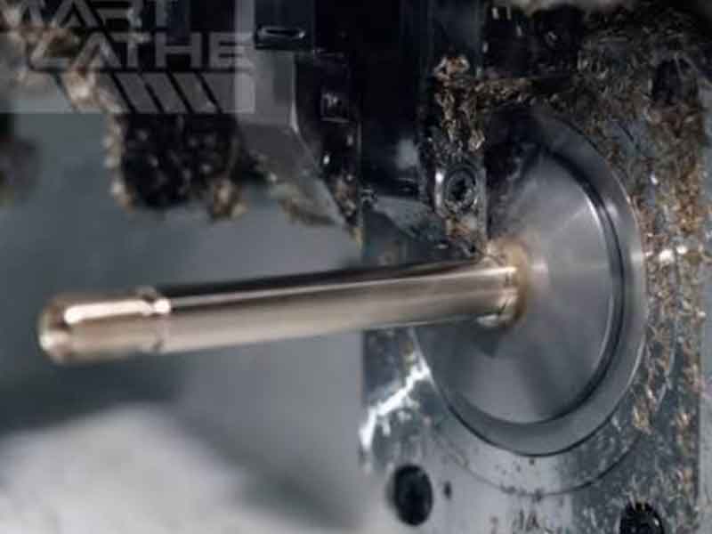
Custom EV charging connector manufacturing is the precision CNC machining, coordinated surface treatment, and assembly-ready component production process — executed on MAZAK mill-turn centers, Swiss CNC turning systems, MAZAK VARIAXIS 5-axis platforms, and precision cylindrical grinding equipment — that produces the metallic bodies, socket bore housing elements, contact spring retention structures, locking mechanism receiver components, sealing feature bodies, and contact arrays of the complete EV charging connector system: not only the vehicle-side inlet receptacle, but the full connector ecosystem including industrial docking connectors, AGV autonomous charging hardware, marine and aviation ground power connectors, battery swap station contact arrays, and custom proprietary connector designs.
For every charging plug in service, there exists a corresponding vehicle-side inlet — a precision machined housing with socket bores registering the mating pin contacts (±0.010mm), an electromagnetic or motor-driven locking receiver retaining the plug during charging (±0.005mm), and IP67 sealing features. Beyond passenger EVs, electrification creates demand for specialized connector types: electric bus pantograph contact shoes at 1,000,000+ contact cycles, electric forklift automatic docking connectors at 50,000+ cycles, AGV charging docking contacts operating within ±3–5mm robot positioning accuracy, and battery swap connectors accumulating 365,000 mating cycles over 10-year station service life — each requiring distinct material, dimensional, and surface treatment specifications that CNCPioneer's full-spectrum connector manufacturing delivers.
-
Vehicle-side inlet socket bore programs — IATF 16949 PPAP Level 3 Socket bore ±0.010mm governing spring contact force, electromagnetic lock receiver bore ±0.005mm governing retention force, and IP67 sealing face flatness 0.010mm/100mm — supplied under IATF 16949:2016 and PPAP Level 3 automotive OEM quality infrastructure for Type 2/CCS2, CCS1, NACS, GB/T 20234.2, and GB/T 20234.3 inlet programs.
-
Industrial high-cycle docking contacts — DLC 2μm · 100,000-cycle verified AGV/AMR docking contact pin OD ±0.002mm CBN-ground to Ra 0.2μm, DLC 2.0μm a-C:H PVD, contact resistance ≤0.8 mΩ at 20N spring contact force — verified at 100,000-cycle accelerated life specification. Electric forklift SB175/SBX75 contact bodies silver-plated at ±0.003mm OD for 50,000-cycle industrial docking life.
-
Battery swap HV contact programs — 365,000-cycle ta-C DLC specification CuCrZr C18150 H02 battery swap contact pins Swiss-CNC turned, CBN-ground to Ra 0.1μm, ta-C DLC 3.0μm PVD at HV 3,000+ — calculated wear depth 0.5μm at 365,000 cycles within 3.0μm ta-C thickness providing 6× safety margin. Contact resistance ≤0.3 mΩ. BeCu AT C17200 socket spring elements retaining 96% pre-load at 365,000 fatigue cycles.
-
40–65% China manufacturing cost advantage Custom EV charging connector machined components at 40–65% below TE Connectivity, Amphenol, Molex, and European precision connector OEM equivalents at identical dimensional accuracy and material compliance — with 48-hour DFM, 24-hour quotation, prototype 3–14 days, and complete IATF 16949/AS9100D documentation included in program pricing.

Why CNCPioneer for Custom EV
Charging Connector Manufacturing?
Among custom EV charging connector manufacturers globally, CNCPioneer's vehicle-side inlet quality governance, industrial high-cycle contact engineering, battery swap 365,000-cycle design capability, proprietary connector DFM service, multi-application portfolio from one IATF 16949 source, and 40–65% China cost advantage establish our factory as the preferred custom EV charging connector manufacturing partner across the complete EV connector ecosystem.
Vehicle-Side Inlet Quality Governance — IATF 16949
Vehicle-side EV charging inlets are automotive components supplied under IATF 16949 requirements to automotive OEM assembly lines. CNCPioneer's IATF 16949:2016 certification, PPAP Level 3 capability, and SPC production monitoring provide the automotive supply chain quality infrastructure for vehicle inlet housing bore programs — socket bore ±0.010mm, locking receiver bore ±0.005mm, IP sealing face flatness 0.010mm/100mm — that automotive OEM procurement requires.
Industrial High-Cycle Contact Engineering — 50,000–100,000 Cycles
Electric forklifts accumulate 100,000+ docking cycles; AGVs accumulate 87,600+ cycles per year. At these cycle counts, contact body OD accuracy ±0.002mm, CBN cylindrical grinding to Ra 0.2μm pre-DLC, and DLC a-C:H 2μm PVD become the governing design parameters. CNCPioneer's industrial connector programs apply Swiss CNC guide bushing precision and DLC coating coordination that 50,000–100,000-cycle industrial connector life requires — verified by 100,000-cycle accelerated life test programs.
Battery Swap 365,000-Cycle Contact Specification
Battery swap connectors accumulate 365,000 mating cycles over 10-year station service life — 36× more than any passenger EV charging connector specification. CNCPioneer's battery swap programs apply ta-C DLC 3.0μm at HV 3,000+, CBN-ground Ra 0.1μm pre-coat surface, BeCu AT C17200 spring elements retaining 96% pre-load at 365,000 cycles, and 100% pressure test per fluid-containing swap connector body — the integrated solution that 365,000-cycle service life requires.
Custom Proprietary Connector Design Service — 48-Hour DFM
Many EV manufacturers need connector designs beyond standardized CCS, GB/T, CHAdeMO, and NACS families. CNCPioneer's 48-hour DFM for custom proprietary connectors covers: contact pitch and diameter from current density and mating cycle analysis; housing bore accuracy from designed spring force; locking receiver geometry from retention force; IP sealing specification from IP rating target; material and plating selection from operating environment — enabling connector design validation before tooling investment.
Multi-Application Portfolio — One IATF 16949 Source
Passenger vehicle inlet programs, commercial vehicle charging connectors, industrial AGV docking contacts, battery swap connector arrays, and custom proprietary connector bodies — all from CNCPioneer under one IATF 16949 quality system, one AS9100D aerospace program track, and one PPAP capability across all connector types. This single-source capability eliminates the supplier management overhead of separate automotive, industrial, and custom connector specialists with different quality systems.
40–65% China Cost Advantage Across All Connector Types
Custom EV charging connector machined components from automotive Tier 1 connector OEMs cost 45–65% more than CNCPioneer's IATF 16949-equivalent programs for identical dimensional accuracy and material compliance. For custom proprietary connector designs, the cost advantage is even larger — large connector OEMs apply premium pricing to non-standard designs. CNCPioneer's flexible Swiss CNC and 5-axis machining platforms produce custom connector geometries at the same cost efficiency as standard designs.
EV Charging Connector Components
We Manufacture
CNCPioneer machines the critical features that define EV charging connector performance — socket bore arrays held to single-digit microns, HV contact pins with sub-milliohm resistance, and wear-resistant coatings verified to 100,000+ cycles. Whether you need inlet housings, plug bodies, or the precision pins and sleeves inside them, we deliver the tolerances that off-the-shelf catalog parts cannot.

Vehicle Inlet Housing Bodies — Type 2 / CCS2 / CCS1 / NACS / GB-T
The vehicle-side interface between the charger and the battery. We CNC machine housing bodies and metallic insert carriers for all major global standards:

Charging Gun Plug Bodies & Contact Carriers
Supply-side plug housings and precision contact carriers for AC/DC charging guns. We machine the structural and conductive components that mate with the vehicle inlet:

Precision Contact Pins, Sleeves & Receptacle Inserts
The conductive heart of the connector. We Swiss-CNC machine power pins, signal contacts, and socket sleeves that carry current from grid to battery — with the tolerances and surface engineering required for HV, high-cycle mating.
Industries & Applications
CNCPioneer's custom EV charging connector manufacturing serves every industry consuming precision connector hardware at automotive-quality tolerances — from EV original equipment manufacturers coordinating vehicle inlet supply programs to battery swap station equipment builders requiring 365,000-cycle HV contact arrays and marine vessel operators requiring IP68 shore power connector bodies.
EV Original Equipment
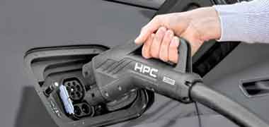
Type 2/CCS2, CCS1, NACS, GB/T 20234.2, and GB/T 20234.3 vehicle inlet housing bore programs for passenger EV production — socket bore ±0.010mm, electromagnetic locking receiver ±0.005mm, IP67 sealing face 0.010mm/100mm, IATF 16949 PPAP Level 3 supply. Per-vehicle inlet kit delivery synchronized to OEM assembly schedules. Volume supply at 800,000+/year with blanket order monthly releases and dedicated MAZAK capacity.
Industrial AGV & Forklift Fleet
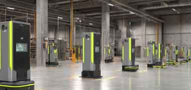
Automatic docking contact programs for AGV/AMR fleets (OD ±0.002mm, DLC 2μm, 100,000-cycle) and electric forklift opportunity charging connectors (SB175/SBX75/DIN 41773 contact body programs, silver-plated, 50,000-cycle). Annual blanket orders with weekly kanban delivery from 3-month CuCrZr and 6061-T6 safety stock. Floor-mounted station contact bodies with IP67 sealing for forklift wheel wash water environments.

Battery Swap Station Equipment
High-cycle battery swap HV contact programs (CuCrZr C18150 H02, ta-C DLC 3.0μm HV 3,000+, OD ±0.002mm, Ra 0.1μm, ≤0.3 mΩ, BeCu AT C17200 spring socket elements, 365,000-cycle specification); multi-pin signal contact arrays (gold 0.5μm); integrated HV + fluid quick-connect body programs (100% pressure test per connector body at 1.5× rated pressure). Complete swap connector kit supply for NIO, CATL/EVOGO, Aulton, and custom platform programs.
EV Charging Connector Manufacturing
Process & Capabilities
CNCPioneer's custom EV charging connector manufacturing process runs on 78+ Swiss CNC lathes with guide bushing support for slender contact pin bodies, 66+ MAZAK mill-turn centers for housing bodies and industrial connector programs, and MAZAK VARIAXIS 5-axis simultaneous machining platforms for complex multi-function integrated connector bodies — with coordinated DLC PVD coating, precision plating, and cylindrical grinding completing the full connector component manufacturing cycle.
48-Hour EV Connector DFM & Engineering Review
Socket bore clearance fit analysis from plug contact pin OD specification · Locking force calculation from receiver bore and plunger geometry · IP sealing face flatness achievability for IP67 or IP68 target · AGV docking contact current density check · Battery swap connector cycle life from DLC wear rate calculation · Marine environment material and plating selection from salt-fog exposure and IP68 requirement · Custom proprietary connector design review (6-input engineering specification → 48-hour DFM with tolerance recommendation, material specification, plating/coating selection, and production pricing) · PPAP Level 3 timeline for automotive OEM vehicle inlet programs.
Swiss CNC Turning — Contact Pin Bodies
78+ Swiss CNC lathes with guide bushing support for slender contact pin bodies at L/D ratios to 20:1 without deflection: CuCrZr C18150 H02 AGV docking contact pins Ø8–16mm OD ±0.002mm Ra 0.2μm · battery swap HV contact pins Ø8–12mm OD ±0.002mm Ra 0.1μm · marine shore power contact pins Ø12–25mm OD ±0.003mm · vehicle inlet contact spring socket bodies Ø4.2–10.2mm +0.010/0 · signal contact pins Ø2.0mm ±0.005mm · micro e-scooter magnetic connector contact pins Ø1.5–3.0mm · wire harness EV connector metallic terminal bodies. 100% laser micrometer OD on all contact pin lots.
MAZAK VARIAXIS 5-Axis — Multi-Function Connector Bodies
Custom proprietary multi-function connector housing bodies (HV power contact bores + signal contact bores + fluid port bores) from one MAZAK VARIAXIS 5-axis program maintaining all inter-feature position accuracy ±0.020mm · vehicle inlet housing bodies with socket bore array, electromagnetic lock receiver, IP sealing face, and bolt pattern from single 5-axis setup · NACS blade contact slot and latch geometry machined in one VARIAXIS program · battery swap connector housing with self-centering guide cone, contact spring seat, and O-ring groove maintaining inter-feature concentricity ±0.003mm · underground mining Ex d connector housing IECEx/ATEX flame path gap ±0.050mm.
Plating & DLC Coating Coordination
Silver ASTM B700 5–25μm (Ni 1.5–5μm underplate; anti-tarnish ASTM B809; XRF ±0.3μm/3 positions per lot) · Gold ASTM B488 Class 1 0.3–1.5μm on signal contacts (XRF ±0.2μm per lot) · a-C:H DLC 2.0μm HV 2,000 for AGV 100,000-cycle contact programs (scratch test adhesion per ASTM C1624) · ta-C DLC 3.0μm HV 3,000+ for battery swap 365,000-cycle contact programs · Hard chrome AMS 2460 with post-plate grinding for heavy-duty latch bodies · Electroless Ni-P MIL-C-26074 for marine aluminum connector housing bodies · Type III hard anodize MIL-A-8625 for aluminum vehicle inlet housing bodies (bore masked). DLC coordination: 3–5 day turnaround through Shenzhen PVD network. Contact resistance verification ≤0.5 mΩ HV power, ≤50 mΩ signal per lot.
EV Connector Materials & Conductivity Verification
CuCrZr C18150 H02 (≥82% IACS eddy current per incoming lot — the decisive material verification step; un-aged CuCrZr at 55% IACS produces 49% higher I²R heating per docking event) · C11000 ETP copper 100% IACS (bus pantograph shoes, AGV floor contact pads) · C26000 cartridge brass (AC vehicle inlet spring socket bodies, high-volume) · C17200 BeCu AT (battery swap 365,000-cycle spring elements) · 6061-T6 (vehicle inlet housing bodies, AGV connector housings, anodized) · 316L stainless (marine IP68, outdoor vehicle inlet bodies) · TC4 titanium (eVTOL multi-function connector bodies, non-magnetic, μᵣ ≤1.005 VSM per lot) · 17-4PH H900 (heavy-duty battery swap locking mechanism bodies) · PEEK (contact isolation bushings, forklift contact isolation) · Inconel 718 (socket spring elements at 50,000+ fatigue cycles) · Invar 36 CTE 1.2 ppm/°C (battery swap alignment structures).
IATF 16949 / AS9100D Quality Documentation
Certificate of Conformance · 100% CMM socket bore array records per housing (bore diameter, perpendicularity, inter-bore pitch from multi-pin CMM fixture) · 100% IP sealing face flatness records per housing · 100% laser micrometer OD per industrial docking and battery swap contact lot · XRF plating thickness records (3 positions per sample, 10 samples per lot) · 4-wire contact resistance records per plating lot · 100% fluid pressure test records per serial number (battery swap and swap fluid-port connectors) · VSM magnetic permeability per TC4 and 316L lot for sensor-adjacent programs · material certifications with heat lot traceability · DLC coating XRF thickness and adhesion scratch test per coating lot · PPAP Level 3 for automotive vehicle inlet OEM programs · AS9100D documentation for aviation eGSE programs · AS9102 FAIR for custom proprietary connector programs · Records retained 20 years.
Materials for Custom EV
Charging Connector Programs
EV charging connector material selection is governed by electrical conductivity at rated current, hardness and wear resistance at mating cycle count, IP rating corrosion environment, mass sensitivity for portable connectors, and operating temperature range. CuCrZr C18150 H02 dominates power contact programs as the practical optimum — 82% IACS conductivity, 500°C softening temperature, and precision machineability at ±0.002mm OD.
CuCrZr C18150 H02
≥82% IACS · 500°C softening · The dominant power contact alloy for DC fast charge contacts, AGV docking pins, and battery swap HV contacts — the combination of 82% IACS conductivity (versus 28% for C26000 brass) minimizing I²R heating per amp-hour of charge, 500°C softening temperature resisting contact annealing under 100A+ current heating events, and precision Swiss CNC machineability at ±0.002mm OD makes CuCrZr the required alloy for every high-current, high-cycle EV connector contact program. CNCPioneer verifies CuCrZr at ≥82% IACS by eddy current conductivity measurement on every incoming material lot — the decisive verification step because un-aged CuCrZr at 55% IACS produces 49% higher I²R heating per docking event, accelerating contact degradation.
C26000 Cartridge Brass
28% IACS · Excellent formability · AC vehicle inlet spring socket bodies, signal contact bodies, standard forklift SB175/SBX75 contact pins, and high-volume connector contact programs where 28% IACS conductivity is adequate for AC charging currents (L1/L2/L3 at 16–32A per contact) and where C26000's superior machinability and lower material cost versus CuCrZr provide decisive manufacturing economics. C26000 tinned or silver-plated for connector contact protection; DIN 41773 forklift contact bodies in C26000 to European forklift connector dimensional standards. Vehicle inlet AC socket spring bodies in C26000 heat-treated for spring property; not recommended for DC fast charge contacts above 50A.
C11000 ETP Copper
100% IACS · Maximum conductivity · Electric bus pantograph contact shoe faces and AGV floor-mounted contact pads where maximum electrical conductivity at 500–750A DC minimizes resistive losses at the sliding contact interface. C11000 copper pantograph shoes machined to face flatness 0.050mm/500mm for uniform current distribution across the full contact width — non-flat shoes concentrate current at high-pressure points, creating hotspot erosion that reduces shoe life by 60–70% at 500A DC. Silver 5–10μm ASTM B700 on copper shoe face for outdoor urban tarnish resistance in city bus environments with sulfur dioxide and hydrogen sulfide pollutant exposure.
C17200 BeCu AT
HV 360–440 AT · Superior fatigue strength · The mandatory spring contact material for battery swap connector socket springs at 365,000-cycle specification. BeCu AT retains 96% of initial spring pre-load at 365,000 fatigue cycles — versus 304 stainless losing 60–70% at 365,000 cycles from stress relaxation, and Inconel 718 retaining 95% at 4× cost and difficulty to form. Spring seat bore machined to ±0.010mm for consistent spring pre-load at rated pin insertion depth. BeCu AT specified for all socket spring elements in connectors accumulating more than 30,000 mating cycles; 304 stainless adequate below 10,000 cycles; Inconel 718 where BeCu AT cannot be sourced or formed to required spring geometry.
Aluminum 6061-T6
Lightweight · Anodizable · The primary structural material for vehicle inlet housing bodies, AGV connector housings, and connector structural arm bodies. 6061-T6 vehicle inlet housing bodies receive Type III hard anodize (MIL-A-8625) for automotive-grade scratch resistance in vehicle body panel environments — bore areas masked during anodize to preserve ±0.010mm socket bore diameter compliance. AGV guide cone bodies in 6061-T6 for minimum pantograph mass enabling rapid rise-fall cycle dynamics. Anodize allowance machined into housing bore and OD dimensions before anodize; post-anodize CMM confirms dimensional compliance in final treated condition.
316L Stainless
IP68 corrosion resistance · Marine H₂S compatibility · The required external housing material for marine shore power connectors operating in continuous salt-water spray, harbor hydrogen sulfide atmosphere, and immersion environments. 316L external housing enclosing C11000 copper or CuCrZr contact body provides dual-material architecture: copper conductivity at contact interfaces, stainless corrosion protection at external surfaces. Passivation ASTM A967 on all 316L external surfaces; electroless Ni-P 10μm on copper contact body external surfaces for IP68 marine environment corrosion protection. Non-magnetic 316L (μᵣ ≤1.005 per VSM verification) for vehicle inlet housing programs adjacent to magnetic navigation or ADAS sensor systems.
TC4 Titanium AMS 4928
Non-magnetic · Lightweight · Premium corrosion resistance · eVTOL multi-function integrated connector housing bodies where minimum mass combined with non-magnetic property (μᵣ ≤1.005 VSM per lot — verified against aircraft navigation systems) and 880 MPa yield for mechanical durability. Titanium TC4 multi-function connector bodies machined on MAZAK VARIAXIS 5-axis from single-piece AMS 4928 bar, incorporating HV power contact bores, signal contact positions, and cooling fluid ports in one 5-axis setup maintaining inter-feature position ±0.020mm. MRI-compatible coupling connector bodies for surgical robotic systems where ferromagnetic materials produce MRI artifact interference. VSM magnetic permeability verification per lot on all TC4 programs for programs adjacent to sensing systems.
PEEK Engineering Grade
Electrical isolation · Chemical resistance · 10 MΩ minimum isolation resistance · PEEK contact isolation bushings in electric forklift conductive docking chargers isolating the contact pad from the forklift metallic structure (Ø20–40mm ±0.050mm, ≥10 MΩ isolation resistance at rated battery voltage). PEEK dielectric separator bodies between HV power contacts and signal contacts in multi-function connector housing bodies. PEEK machined to ±0.050mm bore and OD for press-fit retention; no post-machining heat treatment required. Chemical resistance to Galden PFPE and deionized water cooling fluids in integrated cooling connector programs; resistant to ethylene glycol de-icing fluids in airport eGSE connector programs.
Invar 36 — CTE 1.2 ppm/°C
CTE 1.2 ppm/°C · Athermal alignment · Precision alignment structures for battery swap connectors requiring sub-millimeter contact position stability across −20°C to +60°C swap station operating temperature range. Invar 36's coefficient of thermal expansion (1.2 ppm/°C) is 10× lower than 6061-T6 aluminum (23 ppm/°C) and 15× lower than C26000 brass (20 ppm/°C) — at a 80°C operating temperature range, Invar 36 alignment structures expand only 0.010mm/100mm length versus 0.18mm/100mm for aluminum, maintaining contact position stability that swap robot positioning accuracy requires. Used in battery swap station alignment reference structures and guide rail mounting bodies where thermal drift cannot be tolerated across seasonal temperature variation.
Surface Treatments for
Custom EV Charging Connectors
EV charging connector surface treatment selection addresses contact life at specified mating cycle count (DLC ta-C 3μm for 365,000-cycle battery swap; a-C:H 2μm for 100,000-cycle AGV; silver ASTM B700 for standard connectors), tarnish resistance in outdoor and marine environments (silver 25μm; anti-tarnish ASTM B809), and housing corrosion protection for IP-rated outdoor and marine connector bodies (Type III anodize; electroless Ni-P; passivation ASTM A967).
Silver Plating — ASTM B700 · 5–25μm
The primary surface treatment for EV charging connector power contacts — applied at 5–10μm for standard EV charging plug and inlet contacts, 15μm for AGV industrial docking contacts, and 25μm for marine shore power connector contacts in harbor hydrogen sulfide atmospheres where AgS tarnish formation accelerates silver surface resistance degradation. All silver plating on Ni 1.5–5μm underplate per ASTM B689 for adhesion and diffusion barrier; anti-tarnish treatment ASTM B809 standard on all outdoor and marine silver programs. XRF thickness verification ±0.3μm at 3 positions per 10-sample lot. Contact resistance ≤0.5 mΩ HV power contacts, ≤50 mΩ signal contacts per plating lot. 4-wire milliohmmeter verification at rated contact force per lot before shipment.
Gold Plating — ASTM B488 Class 1 · 0.3–1.5μm
Signal and low-current contact plating for CAN bus, BMS communication, pilot/proximity contact, and CAN+/CAN− signal contacts in vehicle inlet housings, battery swap connector signal arrays, and multi-function proprietary connector signal positions. Gold's tarnish-free surface (no oxide formation) maintains signal contact resistance stability across the connector's full service life — critical for vehicle inlet CP and PP pilot contacts where contact resistance variation triggers EVSE communication errors and charging interruptions. Applied at 0.3–0.5μm for standard signal contacts and 1.0–1.5μm for battery swap signal contacts at 365,000-cycle high-cycle service. XRF thickness verification ±0.2μm at 3 positions per 10-sample lot. Contact resistance ≤50 mΩ signal contacts per lot.
ta-C DLC Coating — 3.0μm · HV 3,000+ · Battery Swap
Tetrahedral amorphous carbon (ta-C) DLC at 3.0μm PVD HV 3,000+ for battery swap HV contact body programs at 365,000-cycle specification — 2.25× harder than a-C:H DLC (HV 2,000), providing 2.25× longer wear life from Archard's wear coefficient scaling with hardness squared. Applied over CBN-ground Ra 0.1μm base surface: DLC on Ra 0.1μm achieves calculated wear depth 0.5μm at 365,000 cycles within 3.0μm ta-C thickness, providing 6× safety margin. ta-C DLC friction coefficient μ = 0.05–0.08 versus silver's μ = 0.25, reducing contact sliding energy 68–80% per swap event. XRF coating thickness ±0.3μm per lot; scratch test adhesion ASTM C1624; contact resistance ≤0.3 mΩ at rated contact force per coating lot. 3–5 day DLC turnaround through Shenzhen PVD network.
a-C:H DLC Coating — 2.0μm · HV 2,000 · AGV 100,000-Cycle
Hydrogenated amorphous carbon (a-C:H) DLC at 2.0μm PVD HV 2,000 for AGV/AMR automatic docking contact pin programs at 100,000-cycle specification. Three simultaneous mechanisms extending contact life: HV 2,000 hardness is 20× harder than silver (HV 50–90) producing 750× lower Archard wear coefficient; friction coefficient μ = 0.05–0.10 versus silver's μ = 0.20–0.30 reducing per-docking sliding energy; fretting resistance preventing micro-cold-welding at asperity contacts under ±0.5mm lateral sliding amplitude per docking event. Applied over CBN-ground Ra 0.2μm base surface (mandatory — DLC on Ra 0.8μm from turning reduces AGV contact life from 100,000 cycles to 35,000–50,000 cycles). 100,000-cycle accelerated life test verified: post-test contact resistance 0.92 mΩ vs. 0.68 mΩ initial — within ≤1.0 mΩ specification.
Electroless Ni-P — MIL-C-26074 · Marine & Outdoor
Uniform corrosion protection for aluminum connector housing external surfaces in marine, outdoor, and industrial corrosive environments. Electroless Ni-P (mid-phosphorus 8–10% P for balanced hardness and corrosion; high-phosphorus 10–12% P for maximum marine corrosion resistance) applied at 10–25μm on 6061-T6 aluminum connector bodies for outdoor commercial vehicle charging station environments, and at 25μm on aluminum AGV floor-station contact body external surfaces for forklift wheel wash water exposure. Uniform deposition on complex housing geometries — including bores, slots, and O-ring grooves — maintaining critical bore and groove dimensions within ±0.003mm of pre-plate machined dimensions with plating allowance pre-built into machined dimensions. Applied in combination with passivation ASTM A967 on 316L stainless internal housing components.
Type III Hard Anodize — MIL-A-8625 · Vehicle Inlet Housings
Automotive-grade scratch and abrasion resistance for 6061-T6 aluminum vehicle inlet housing bodies in vehicle body panel environments where uncoated aluminum would sustain surface damage from charging plug repeated insertion cycles, debris contact, and automotive assembly handling. Type III hard anodize (HV 400+, 25μm) applied with socket bores masked — preserving the ±0.010mm socket bore diameter accuracy without anodize build-up on precision bore surfaces. Post-anodize dimensional verification: all non-masked external surfaces measured to confirm anodize build-up within design allowance; masked bore diameters air-gauged to confirm bore compliance in the anodized housing. Anodize allowance (typically 0.012–0.015mm per surface on external dimensions) is machined-in at the CNC turning stage with pre-anodize dimension targets specified to achieve post-anodize dimensional compliance.
All surface treatments on EV charging connector programs — silver ASTM B700, gold ASTM B488, ta-C DLC 3μm PVD, a-C:H DLC 2μm PVD, hard anodize Type III MIL-A-8625, electroless Ni-P MIL-C-26074, passivation ASTM A967, Alodine Class 3 MIL-DTL-5541 — are documented with treatment certifications, XRF plating thickness records, contact resistance records per lot, and post-treatment dimensional verification. Plating and coating allowances are machined-in at the CNC turning stage and confirmed post-treatment by air gauge, laser micrometer, or CMM — ensuring dimensional specifications are met in the final delivered condition. Treatment selection guidance and dimensional allowance calculation are included in CNCPioneer's 48-hour DFM at no additional cost.
Quality Assurance for
Custom EV Charging Connector Manufacturing
EV charging connector quality assurance addresses vehicle inlet socket bore arrays with 100% CMM per housing body, IP sealing face flatness verification per housing, 100% laser micrometer OD on all industrial contact lots, 100% pressure test per fluid-containing battery swap connector body, and XRF plating thickness verification per lot — the measurement infrastructure that zero-defect EV connector supply requires across automotive OEM, industrial fleet, and battery swap station programs.
Engineering Contract Review & 48-Hour DFM
48-hour DFM covering: socket bore clearance fit analysis from plug contact pin OD specification and inlet socket bore design; locking mechanism receiver bore accuracy from retention force target and plunger geometry; IP sealing face flatness achievability for IP67 or IP68 target; AGV docking contact current density and thermal check; battery swap connector cycle life calculation from ta-C DLC wear rate at specified mating frequency; marine environment material and plating compatibility matrix; custom proprietary connector design producibility assessment (6-input specification → DFM with tolerance recommendation, material specification, plating/coating, and production pricing). All drawing ambiguities resolved before machining — non-conforming connector housing bodies scrap expensive materials and lose lead time that prototype programs cannot recover.
Material & Conductivity Verification
SII XRF composition on every material lot: CuCrZr C18150 (Cr 0.5–1.5%; Zr 0.03–0.30%); C11000 (Cu ≥99.90%); C26000 (Cu 68.5–71.5%); 6061-T6 (Mg 0.80–1.20%; Si 0.40–0.80%); 316L (C ≤0.030%; Mo 2.0–3.0%); TC4 (Al 5.5–6.75%; V 3.5–4.5%); 17-4PH (Cr 15.0–17.5%; Ni 3.0–5.0%); PEEK (FTIR virgin confirmation). Eddy current conductivity: CuCrZr ≥82% IACS per incoming lot — mandatory for all DC power contact programs; sub-specification conductivity triggers material rejection regardless of composition compliance. Hardness: CuCrZr H02 HV ≥160; 17-4PH H900 HRC 44–47; BeCu AT per C17200 specification. Magnetic permeability: VSM per lot on TC4 and 316L for programs adjacent to navigation or ADAS sensor systems (μᵣ ≤1.005 specification).
In-Process CMM, Laser Micrometer & Air Gauge Control
Vehicle inlet socket bore array: 100% CMM on socket bore diameter after finish boring; bore perpendicularity per bore; inter-bore pitch from CMM multi-pin fixture before proceeding to sealing face machining. IP sealing face: CMM 9-point flatness measurement per housing body batch — any housing outside 0.010mm/100mm flatness specification quarantined before sealing groove machining. AGV docking contact OD: 100% laser micrometer at Swiss CNC output; in-process air gauge every 50 contacts with automatic NC offset correction maintaining ±0.002mm without operator intervention. Battery swap connector fluid port O-ring groove: CMM per batch; 100% pressure test before DLC dispatch. Locking receiver bore: CMM after finish boring; concentricity to socket bore array axis per housing.
Final Dimensional Inspection — 100% Per Component
100% CMM per vehicle inlet housing body: socket bore diameter, bore perpendicularity, inter-bore pitch from multi-pin fixture, electromagnetic lock receiver bore, IP sealing face flatness, O-ring groove width and depth, mounting bolt pattern true position. 100% laser micrometer OD per industrial docking and battery swap contact: diameter ±0.002mm at 3 contact-zone positions per pin; ovality check at each position. XRF plating: gold ±0.2μm at 3 positions per 10-sample lot; silver ±0.3μm per lot; DLC ±0.3μm per coating lot. 4-wire contact resistance: HV power ≤0.5 mΩ (≤0.3 mΩ battery swap DLC contacts); signal ≤50 mΩ per plating lot at rated contact force. Marine connector IP68 dual O-ring groove: both grooves CMM per housing body — depth tolerance Kalrez specification ±0.008mm.
100% Pressure Test — Fluid-Containing Connectors
Battery swap connectors with cooling fluid ports: 100% pressure decay test at 1.5× rated fluid pressure per connector body — NIST-traceable transducer ±0.005 bar; 30-second hold; zero pressure decay; records per serial number. Failed pressure test triggers O-ring groove CMM re-measurement and dimensional investigation before reject disposition. Poppet valve body pressure test: 100% per valve body at 1.5× rated coolant pressure per serial number, governing Kalrez O-ring groove depth ±0.010mm compliance. Marine connector IP68 pre-immersion verification: 10 bodies per production lot submerged 1m for 30 minutes — zero moisture ingress verified by internal desiccant indicator post-test. Proprietary multi-function connector 100% combined HV/signal/fluid functional test: all functions verified simultaneously in assembled connector before shipment.
Documentation Package
Certificate of Conformance · 100% CMM socket bore array records per vehicle inlet housing (bore diameter, perpendicularity, inter-bore pitch, lock receiver bore, sealing face flatness, O-ring grooves, bolt pattern) · 100% IP sealing face flatness records per housing · 100% laser micrometer OD records per industrial and battery swap contact lot · XRF plating thickness records (3 positions per sample, 10 samples per plating lot) · 4-wire contact resistance records per plating lot · 100% fluid pressure test records per serial number (fluid-containing connectors) · VSM magnetic permeability per TC4 and 316L lot · Material certifications with heat lot traceability · DLC coating XRF thickness and ASTM C1624 adhesion scratch test per coating lot · PPAP Level 3 for automotive vehicle inlet OEM programs · AS9100D documentation track for aviation eGSE programs · AS9102 FAIR for custom proprietary connector programs · All records retained 20 years.
IATF 16949 Quality System for
Custom EV Charging Connector Manufacturing
CNCPioneer's IATF 16949 and AS9100D certified EV charging connector quality system addresses the four quality dimensions specific to vehicle inlet housing bodies and industrial connector contact programs: socket bore CMM per housing with multi-pin fixture inter-bore pitch verification, IP sealing face flatness per housing body, 100% pressure test per fluid-containing battery swap connector body, and PPAP Level 3 bridge to volume automotive OEM vehicle inlet supply chain qualification.
Socket Bore CMM Per Vehicle Inlet Housing
Every vehicle inlet housing body — CCS2, CCS1, NACS, GB/T 20234.2, GB/T 20234.3 — receives 100% CMM verification on the complete socket bore array: individual bore diameters (±0.010mm), bore perpendicularity to housing face (0.010mm per bore), and inter-bore pitch from a multi-pin CMM fixture that simultaneously registers all socket positions against the CCS2/GB/T/NACS geometric specification (±0.020mm inter-bore pitch). The multi-pin fixture measurement is the critical CMM step: individual bore diameter compliance does not verify that all bores are positioned correctly relative to each other — and a socket array with individually-correct bore diameters but incorrect pitch produces plug-inlet mating interference that damages contact pins at first insertion. 100% multi-pin CMM per housing body (not sampled) eliminates this escape mechanism from the vehicle inlet supply chain.
- 100% CMM socket bore array per housing body
- Multi-pin fixture inter-bore pitch ±0.020mm
- Locking receiver bore ±0.005mm per housing
IP Sealing Face Flatness Per Housing Body
Vehicle inlet IP67 compliance depends on uniform gasket compression across the inlet housing sealing face — and sealing face flatness (0.010mm/100mm specification) is the geometric requirement governing gasket compression uniformity. CNCPioneer verifies IP sealing face flatness by CMM 9-point measurement on every vehicle inlet housing body before sealing groove machining — any housing outside 0.010mm/100mm flatness specification is quarantined before the sealing groove is cut, preventing the production of housings where the sealing groove geometry is correctly machined in a housing whose face geometry cannot achieve IP67 compliance after the sealing groove is added. This sequential verification protocol — face flatness verified before groove machining — eliminates the most common vehicle inlet IP failure root cause, where correctly-dimensioned grooves in non-flat housing faces produce non-uniform gasket compression.
- CMM 9-point flatness per housing body before groove
- 0.010mm/100mm flatness specification
- O-ring groove depth ±0.010mm per housing CMM
100% Pressure Test Per Fluid-Containing Connector
Battery swap connectors with integrated cooling fluid quick-connect bodies receive 100% pressure decay test per connector body before DLC coating and plating dispatch: NIST-traceable transducer ±0.005 bar, test pressure 1.5× rated fluid pressure, 30-second hold, zero pressure decay criterion, records traceable per serial number. 100% (not sampling) is required because fluid port O-ring groove dimensional variation causing seal gap is a low-frequency failure mode (Cpk ≥1.67 production process produces <1 ppm dimensional rejects) but 1 ppm at battery swap station volumes (10,000+ connector bodies/year) produces 10+ fluid-leak field failures annually — an unacceptable field failure rate for a connector body whose fluid leak contaminates the vehicle battery pack. 100% pressure test per serial number is the only measurement approach that provides zero-escape assurance on fluid port integrity.
- 100% pressure test per connector body serial number
- 1.5× rated pressure / 30s / zero decay criterion
- Records per serial number — NIST-traceable transducer
PPAP Level 3 & Automotive OEM Vehicle Inlet Qualification
PPAP Level 3 qualification for automotive OEM vehicle inlet supply chains: design records, process flow (socket bore machining sequence, sealing face flatness verification gate, locking receiver bore sequence, anodize masking protocol), PFMEA (covering bore-pitch error from multi-pin fixture, sealing face non-flatness, locking receiver bore oversize, IP sealing groove depth, anodize bore exposure), control plan, MSA Gage R&R on CMM multi-pin socket bore fixture and IP sealing face measurement system (≤10% gage R&R on all critical dimensions), initial capability studies (Cpk ≥1.67 on IATF special characteristics: socket bore diameter, inter-bore pitch, lock receiver bore, sealing face flatness), and part submission warrant. Generated on the same CMM programs used in volume production — prototype to PPAP qualification represents statistical progression on proven processes. Volume supply at 800,000+ vehicle inlet housing bodies annually with dedicated MAZAK capacity and 3-month CuCrZr/6061-T6/316L safety stock.
- PPAP Level 3 for vehicle inlet OEM supply
- Cpk ≥ 1.67 socket bore / sealing face / lock receiver
- MSA Gage R&R ≤10% on all critical CMM fixtures
Custom EV Charging Connector Manufacturing FAQ
Common questions from EV original equipment manufacturers, battery swap station builders, industrial AGV fleet operators, commercial vehicle charging integrators, marine and aviation ground power OEMs, and custom proprietary EV charging connector designers about CNCPioneer's connector manufacturing capability, vehicle inlet socket bore specifications, DLC contact life, battery swap 365,000-cycle design, and custom connector DFM programs.
The vehicle-side EV charging inlet and the charger-side plug are complementary components of the same mating interface, but their machining specifications differ fundamentally. The charger-side plug contact pin — described on the adjacent EV charging plug and charging gun pages — must achieve tight OD accuracy (±0.002mm for DC power contacts) because the plug contact pin OD directly determines the contact force between the pin and the spring-loaded socket in the vehicle inlet. The vehicle-side inlet socket bore housing body has a different dimensional priority: the socket bore ID (±0.010mm) positions the spring contact elements concentrically to the incoming plug pin, but the inlet housing bore itself does not make primary electrical contact. The critical vehicle-side inlet dimensions are: (1) socket bore array pitch accuracy ±0.020mm between socket centers — the most important inlet housing specification, because socket position deviation greater than ±0.020mm from the standard pin pitch creates plug-inlet binding and potential contact damage during mating; (2) electromagnetic locking receiver bore accuracy ±0.005mm — tighter than the socket bore because the locking plunger fits the receiver bore with a 0.010–0.030mm sliding clearance, and receiver bore oversize allows plug lateral motion during charging producing fretting at the contact interface; (3) IP sealing face flatness 0.010mm/100mm governing IP67 gasket compression uniformity. For a CCS2 DC power contact pin at Ø10.000mm ±0.002mm mating with an inlet socket bore at Ø10.200mm +0.010/0, the designed clearance range is 0.188–0.212mm diametral — deliberate clearance allowing spring contacts to self-center on the incoming pin across the ±3mm lateral alignment tolerance that users introduce during manual mating. CNCPioneer's supply of both plug contact pin OD (±0.002mm) and inlet socket bore ID (±0.010mm) from the same factory enables matched-interface verification that eliminates dimensional interface uncertainty from two independently-compliant but unverified mating partners.
Electric forklift and AGV automatic docking contacts accumulate mating cycles at rates that have no parallel in passenger EV charging — a forklift opportunity charging at every break during a 20-year service life accumulates 100,000+ docking cycles, while an AGV charging at its home station 8 times per shift over 10 years accumulates 60,000+ cycles — both exceeding 10× the maximum mating cycle specification of any standard passenger EV charging connector. Standard silver plating (10–15μm) on Ra 0.4μm contact pin surface achieves 10,000–15,000 mating cycles before silver is worn through from asperity abrasion and fretting — adequate for passenger EV DC charging guns at public stations but failing at approximately 15% of the required industrial service life. DLC (Diamond-Like Carbon) coating extends contact life by three simultaneous mechanisms: (1) Hardness — DLC at HV 2,000–3,500 is 20–70× harder than silver (HV 50–90); Archard wear coefficient k_DLC is approximately 750× lower than silver at equivalent contact stress. (2) Friction — DLC friction coefficient μ = 0.05–0.10 versus silver's μ = 0.20–0.30 reduces energy per sliding contact event by 68% from friction reduction alone. (3) Fretting resistance — DLC's hardness prevents micro-cold-welding at asperity contacts under repeated micro-motion that degrades silver contact resistance from ≤1 mΩ initial to 5–10 mΩ at 12,000 cycles. Pre-DLC surface preparation is critical: DLC on Ra 0.1–0.2μm from CBN cylindrical grinding produces 100,000-cycle life; DLC on Ra 0.8μm from turning produces 35,000–50,000-cycle life — emphasizing that CBN grinding to Ra 0.2μm before DLC coating is the mandatory manufacturing sequence, not an optional quality step. CNCPioneer's 100,000-cycle accelerated life test case study delivered post-test contact resistance 0.92 mΩ (initial 0.68 mΩ) — within ≤1.0 mΩ specification. PASS.
Battery swap connector contacts accumulate 365,000 mating cycles over a 10-year station service life (100 swaps/day × 365 days × 10 years) — 36× more than industrial forklift contacts and far beyond any passenger vehicle charging connector specification. This cycle count places battery swap contacts in a fundamentally different engineering category where no noble metal plating alone provides adequate contact life, fatigue becomes the dominant failure mode for spring contact elements, and dimensional stability under repeated thermal cycling governs whether contact force remains within specification across the service life. The material and coating solution builds from the AGV contact solution but requires additional measures for the 3.65× higher cycle count. Contact pin material: CuCrZr C18150 H02 (82% IACS; 500°C softening temperature — un-aged CuCrZr at 55% IACS produces 49% higher I²R heating per swap event). Contact pin surface: CBN cylindrical grinding to Ra 0.1μm (not Ra 0.2μm used for 100,000-cycle AGV contacts — at 365,000 cycles, Ra 0.2μm versus Ra 0.1μm adds approximately 15,000 cycles of additional wear life from lower asperity height penetrating DLC sooner). DLC coating: ta-C (tetrahedral amorphous carbon) 3.0μm at HV 3,000+ — ta-C's higher hardness provides 2.25× longer wear life than a-C:H at HV 2,000 from Archard's wear coefficient scaling with hardness squared; ta-C on Ra 0.1μm base achieves calculated wear depth 0.5μm at 365,000 cycles within 3.0μm ta-C thickness with 6× safety margin. Socket spring element: C17200 BeCu AT retaining 96% of initial spring pre-load at 365,000 fatigue cycles — versus 304 stainless losing 60–70% from stress relaxation at 365,000 cycles, and Inconel 718 retaining 95% at 4× cost and forming difficulty. Each swap event generates approximately 26°C contact temperature rise from I²R heating — rapidly conducted to contact body bulk during the 3–5 second non-current interval between swap events, producing negligible cumulative temperature fatigue on CuCrZr with 500°C softening temperature across 365,000 swap events.
Yes — CNCPioneer's three EV charging connector pages (/ev-charging-plug-machining/, /ev-charging-gun-machining/, and this page) represent a complete EV charging connector manufacturing capability covering both sides of every mating interface. This matched-supply capability eliminates the dimensional interface uncertainty that arises when plug and inlet components are sourced from different suppliers with independent dimensional compliance but no inter-part verification. The specific advantage: for a CCS2 DC power contact pin at Ø10.000mm nominal ±0.002mm (CNCPioneer plug page standard) mating with an inlet socket bore at Ø10.200mm nominal ±0.010mm (this page standard), the designed clearance range is 0.188–0.212mm diametral (0.094–0.106mm radial). This clearance is deliberate — it allows the spring socket contacts within the inlet to self-center on the incoming pin across the ±3mm lateral plug-to-inlet alignment tolerance that users introduce during manual mating. When plug contact pin OD and inlet socket bore ID are sourced from independent suppliers, each supplier certifies their part as individually within tolerance, but the combined plug-to-inlet clearance stack could be anywhere within ±0.012mm of the design target — an acceptable variation for most charge-and-go charging scenarios but potentially problematic for high-cycle charging stations where plug insertion force consistency determines user experience. CNCPioneer's supply of both sides of the mating interface enables air-gauge verification of plug contact pin OD against inlet socket bore ID from the same factory, confirming that the as-manufactured clearance is within the 0.188–0.212mm design window rather than only within each part's individual tolerance. For automotive OEM vehicle inlet programs requiring PPAP Level 3, CNCPioneer can include inter-part clearance verification data in the PPAP submission — an additional quality evidence level that single-side suppliers cannot provide.
Prototype lead times: 6061-T6 Type 2/CCS2 vehicle inlet housing body (socket bore array, locking receiver, IP sealing face, FAIR) 8–12 business days; GB/T 20234.3 DC vehicle inlet housing body (9-bore array, electromagnetic lock receiver, IP67 face) 8–12 days; NACS vehicle inlet housing body (blade contact slot array, latch notch, IP67) 7–10 days; C11000 copper pantograph contact shoe body (face flatness 0.050mm, 5-piece set) 6–9 days; CuCrZr C18150 H02 AGV/AMR docking contact pin set (OD ±0.002mm, DLC a-C:H 2μm, guide cone body, 25-piece) 5–8 days; battery swap HV contact body set (±0.002mm OD, ta-C DLC 3μm, spring retention seat, 25-piece) 6–9 days; 316L stainless marine shore power connector body (IP68 dual O-ring, silver 25μm, passivated, FAIR) 8–12 days; custom proprietary multi-function connector body (5-axis HV + signal + fluid integration, 100% pressure test, FAIR) 10–14 days. PPAP Level 3 for automotive vehicle inlet programs: 6–8 weeks from prototype approval. Volume production pricing examples (annual volume vs. Type 2/CCS2 vehicle inlet housing body): 50,000–200,000 pc at $45–$65; 200,000–800,000 pc at $31–$45; 800,000–2,500,000 pc at $21–$31; 2,500,000+ pc at $14–$21 — representing 40–65% below European Tier 1 automotive connector OEM equivalent. Volume supply features: pre-purchased CuCrZr H02, C11000 copper, C26000 brass, and 6061-T6 safety stock; 3-month forward inventory for vehicle OEM blanket programs; DLC coordination 5-day transit from machining to DLC PVD facility; IATF 16949 PPAP Level 3 for automotive programs; 100% fluid pressure test per battery swap connector body serial number; per-vehicle or per-system connector kit supply with lot traceability documentation.
Get a Quote for Custom EV Charging Connector Manufacturing
Submit your vehicle inlet CAD files, industrial docking connector specifications, battery swap system contact array requirements, marine or aviation ground power connector designs, or proprietary connector concept documentation and receive a competitive quotation within 24 hours and complete engineering DFM within 48 hours — covering vehicle inlet socket bore clearance fit analysis, locking mechanism receiver bore accuracy, IP sealing face flatness achievability, AGV docking contact cycle life calculation, battery swap connector contact life from ta-C DLC wear rate, marine environment material and plating selection, and custom proprietary connector design review from 6-input specification to complete DFM package.