
Chamber-Focused Drawing Review
Review the chamber envelope, access openings, wall sections and tool access before machining. Identify features that affect fixturing, finishing or inspection while the design can still be refined.
Custom semiconductor vacuum chamber machining from your drawings. CNCPioneer machines stainless steel and aluminum chamber bodies, covers and port interfaces, with sealing surfaces, finishing and inspection planned around your equipment requirements.

A custom semiconductor vacuum chamber starts with the geometry your equipment needs: the chamber body, access cover, pumping connection, process ports and mounting interfaces. CNCPioneer provides CNC machining for these features and the matching components shown on your drawings.
Our drawing review connects chamber dimensions with material selection, sealing-face requirements, port alignment and surface preparation. Share the operating environment and acceptance criteria so machining, finishing, cleanliness and any additional testing can be defined for your order.
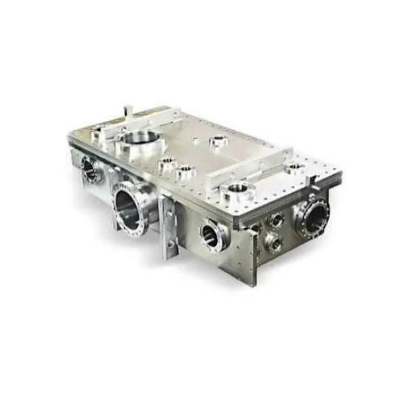
Plan the chamber body and its mating features together, from drawing review through machining and final inspection.
Review the chamber envelope, access openings, wall sections and tool access before machining. Identify features that affect fixturing, finishing or inspection while the design can still be refined.
Plan machining setups around the chamber datum system. Control the relationship between port bores, sealing faces and mounting features using the tolerances on the approved drawing.
Identify gasket faces, O-ring grooves and specified CF knife-edge profiles as critical features. Include edge protection and surface-condition checks in the agreed inspection plan.
Review stainless steel or aluminum grade, stock condition and finishing allowances together. Identify surfaces that need masking, controlled roughness or dimensional checks after treatment.
Coordinate the chamber body with covers, flanges and mounting interfaces using the same drawing revision. Define mating dimensions and purchased-component interfaces before releasing the order.
Agree material certificates, dimensional results, finish records and packaging requirements with the quotation. Additional vacuum testing or specialist preparation is scoped separately when requested.
Representative chamber configurations and supporting interfaces. Send your drawing to confirm the geometry, material and manufacturing scope for your project.
Chamber bodies and access covers with machined pockets, perimeter sealing faces and side ports. Define the internal envelope, wall sections and cover interface on your drawing.

Chamber bodies with several flanged connections for equipment integration. Port locations, bore alignment and mating faces are controlled from the specified chamber datums.

Custom chamber housings with equipment attachment features. Review mounting pads, support interfaces, access clearances and the relationship between these features and the process ports.

Matching CF flange interfaces made to the specified drawing. Identify flange size, sealing profile, bolt pattern and surface-finish requirements before machining.
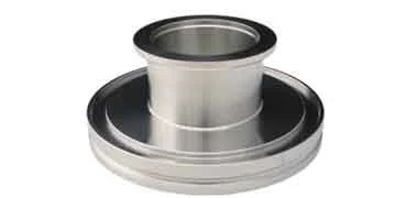
Supporting KF connections and adapters for the chamber layout. Confirm mating sizes, centering-ring interfaces, clamp clearance and any transition geometry.
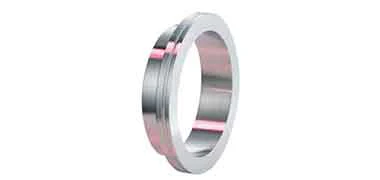
Supporting ISO-K flange interfaces with the required bores, sealing faces and fastening features. Supply the mating connection details and inspection requirements with your enquiry.
Custom chamber machining for semiconductor equipment projects. Each application is reviewed against its process environment, port layout, material and acceptance requirements.

Chamber bodies, access covers and mounting interfaces for OEM equipment builds. Coordinate the installation envelope, service access, pumping ports and mating components before machining.

Machined chambers and flange interfaces for deposition equipment. Define substrate access, source connections, process ports and the surface preparation required for the selected process.

Chamber bodies and covers for etch equipment projects. Review process chemistry, material selection, replaceable interfaces and sealing surfaces against the equipment specification.
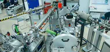
Chamber housings and beamline connection interfaces with drawing-defined bore locations. Establish alignment datums, access openings and mounting features for integration with the equipment.

Chamber bodies with source, viewport and instrumentation ports arranged to the system drawing. Specify bake-out conditions, material, seal type and surface preparation for technical review.

Chamber housings and precision mounting interfaces for vacuum-based inspection tools. Coordinate sensor access, stage clearances, port positions and critical mechanical datums.
Explore machining capabilities, material options and quality support for semiconductor components.
Explore semiconductor machiningMaterials
Stainless steel and aluminum chamber materials are reviewed against process chemistry, temperature, surface preparation and mating-component requirements. Confirm the grade and stock condition on your drawing.
An option for stainless chamber bodies, covers and flange interfaces. Specify the required material condition, finishing route, cleaning requirements and material certification for your equipment.
Consider when the equipment specification calls for 316L chamber surfaces or interfaces. Review compatibility with the actual process environment, operating temperature and selected surface treatment.
An option for machined chamber bodies, covers and mounting features where aluminum is specified. Confirm stock form, thermal conditions, surface treatment and sealing details with the drawing.
Finish selection
Define vacuum-exposed surfaces, sealing faces and external features separately. Finishing allowances, masking, cleaning and packaging are agreed for the specified material and chamber design.
Machine functional faces to the drawing-defined finish. Identify sealing areas and inspection locations so tool marks, edges and surface condition can be assessed against agreed criteria.
Review electropolishing for the selected stainless grade and geometry. Plan treatment allowances and checks on critical dimensions, sealing profiles and surfaces after processing.
Specify the required passivation process and acceptance records. Confirm compatibility with the chamber material, surface condition and any other finishing operations.
Review anodizing only where permitted by the chamber specification. Identify vacuum-exposed surfaces, sealing faces and fits that require masking or dimensional allowance.
Define the cleaning method and acceptable surface condition before production. Specialist cleaning, cleanliness verification and related records are confirmed with the order.
Agree handling and packaging around the finished chamber. Identify surfaces needing protection and specify bagging materials, part identification and delivery documentation.
Chamber machining enquiries are reviewed for part envelope, material, setup access, finishing and inspection before the production route and delivery schedule are quoted.
Inspection & documentation
Inspect the chamber features that control assembly: the body envelope, port locations, sealing faces, cover interfaces and mounting datums. The inspection scope follows the approved drawing.
Tolerances and surface acceptance follow the approved drawing. Leak testing, bake-out and specialist cleanliness verification require separate review, an agreed method and defined acceptance criteria.
Confirm the certificates, inspection reports and production records needed for your order when sharing your drawing.
We review stainless steel and aluminum chamber bodies, access covers, multi-port housings and matching flange interfaces from customer drawings. Feasibility depends on the part envelope, material, tool access and required tolerances.
Common enquiry options include 304L and 316L stainless steel and 6061-T6 aluminum. The selected grade and stock condition must suit the process environment, thermal requirements and finishing route.
Identify the sealing-face flatness, groove dimensions, port positions, bore alignment and required surface roughness on the drawing. Achievable tolerances are reviewed for the chamber size, material, geometry and treatment sequence.
CF, KF, ISO-K and custom connection interfaces can be reviewed as part of the chamber drawing. Specify the mating size, sealing arrangement, bolt or clamp details and any purchased-component interfaces.
Specify the vacuum-exposed surfaces, required roughness, permitted treatments and cleanliness criteria. Electropolishing, passivation or permitted aluminum treatments are reviewed with the material and geometry; cleaning, handling and packaging requirements are agreed with the quotation.
Include the operating pressure range, permitted leak rate and required test procedure with your enquiry. Helium leak testing, bake-out, specialist cleaning and assembly are confirmed separately in the quotation, with the chamber configuration and acceptance conditions defined.
Prototype and repeat-production enquiries are reviewed using the chamber geometry, material availability, finishing, inspection scope and quantity. Pricing and delivery are confirmed for the specific order.
Send a 2D drawing and available 3D model, material grade, chamber envelope, port layout, sealing details, critical tolerances, surface requirements and order quantity. Include the operating environment, requested tests and delivery documentation.
CUSTOM CNC PARTS
Send your chamber drawing or 3D model, material, port layout, sealing details and order quantity. Add surface preparation, inspection and any requested leak-test requirements so we can review the manufacturing scope and prepare your quote.
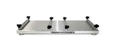 Semiconductor Cooling Plate
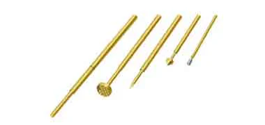 Semiconductor Test Probes
 Semiconductor Wet Etch Spray Nozzles
 Stainless Steel Semiconductor Parts