
Hydraulic Cylinder
Components
CNCPioneer machines complete hydraulic cylinder components for industrial, mobile, marine, agricultural and automation equipment. Barrel boring and honing, piston and rod machining, seal gland boring, matched end caps, tie rods and mounting parts are coordinated under IATF 16949 and AS9100D quality systems, with 24-hour DFM review.
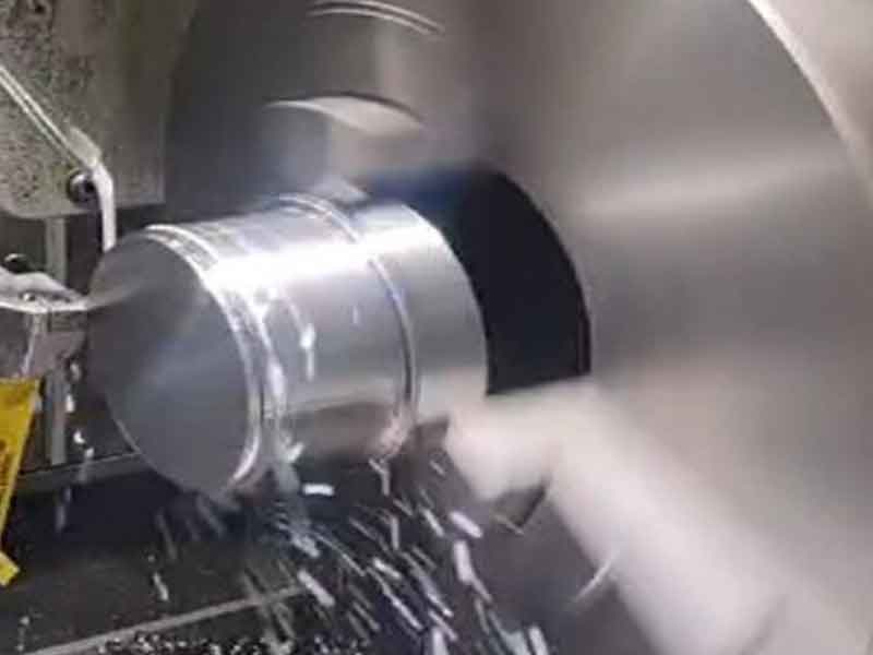
What Are Hydraulic Cylinder
Components?
Hydraulic cylinder components machining produces the pressure-containing, sealing, guiding and mounting parts that convert hydraulic pressure into controlled linear force. CNCPioneer coordinates the machining of barrels, pistons, rods, seal glands, end caps, tie rods and mounting hardware for complete cylinder assemblies.
Each component has a different governing feature: barrel bore geometry and honing, piston seal grooves, rod diameter and surface finish, gland seal cavities, matched end-cap hole patterns, tie-rod length and mounting interfaces. Reviewing these relationships together helps protect running clearance, sealing performance, assembly fit and service life.
-
Complete 7-component manufacturing from one source CNCPioneer produces all seven hydraulic cylinder component types for one cylinder design under one purchase order, one quality record set, and one coordinated delivery — eliminating the inter-supplier compatibility issues that produce leakage, misalignment, or assembly interference when components are sourced from multiple suppliers.
-
Barrel boring and honing to Ra 0.2–0.4μm with cross-hatch pattern CNCPioneer provides cylinder barrel boring to ±0.005–0.010mm and precision honing to Ra 0.2–0.4μm with a 45–60° cross-hatch honing pattern that retains lubricating oil on the bore surface between piston strokes — the bore finish that determines seal life and cylinder leakage performance.
-
Matched cylinder kit verification before shipment All components packaged as a complete cylinder assembly kit with CMM report confirming inter-component dimensional compatibility — barrel bore × piston OD running clearance; rod OD × seal gland seal bore; front/rear cap tie rod hole pattern match — eliminating assembly interference.
-
One matched program for complete cylinder kits Barrels, pistons, rods, seal glands, end caps, tie rods and mounting parts are reviewed as an assembly. CMM checks, matched-kit verification, PPAP support and coating coordination can be included in the production package.

Why CNCPioneer — Hydraulic
Cylinder Components Manufacturer
CNCPioneer combines seven-component coverage, barrel boring and honing, matched cylinder kit verification, piston rod chrome coordination and single-setup end-cap machining for hydraulic cylinder OEMs that need consistent parts across one assembly.
Complete 7-Component Manufacturing from One Source
CNCPioneer produces all seven hydraulic cylinder component types — barrel, piston, rod, seal gland, front end cap, rear end cap, tie rods, and mounting hardware — for one cylinder design under one purchase order, one quality record set, and one coordinated delivery. This eliminates the inter-supplier compatibility issues that produce leakage, misalignment, or assembly interference when components are sourced from multiple suppliers — the matched kit is verified before shipment, not assumed from individual tolerances.
Barrel Boring and Honing to Ra 0.2–0.4μm
CNCPioneer provides cylinder barrel boring to ±0.005–0.010mm and precision honing to Ra 0.2–0.4μm with a 45–60° cross-hatch honing pattern that retains lubricating oil on the bore surface between piston strokes. Bore cylindricity ±0.005mm/300mm precision. This bore finish is the dominant determinant of seal life and cylinder leakage performance — barrels honed above Ra 0.4μm produce 40–60% shorter seal life than barrels at CNCPioneer's honed finish specification.
Matched Cylinder Kit Verification Before Shipment
All components packaged as a complete cylinder assembly kit with CMM report confirming inter-component dimensional compatibility — barrel bore versus piston OD running clearance; rod OD versus seal gland seal bore running clearance; front and rear end cap tie rod hole patterns verified as matched pair within ±0.020mm. The matched kit eliminates assembly interference and ensures the cylinder assembles to design specification without selective fitting or rework.
Piston Rod Chrome Coordination — Turn + Chrome + Grind
CNCPioneer coordinates the complete piston rod supply chain: turning on MAZAK to ±0.010mm pre-chrome; rod end thread turning with concentricity to OD ±0.005mm; straightness verification ±0.05mm/1,000mm; hard chrome plating through qualified partners (0.020–0.040mm); post-chrome grinding to ±0.005mm and Ra 0.05–0.1μm superfinish. Integrated supply: procure, machine, chrome, grind, inspect, ship as one rod delivery program — no customer coordination across separate subcontractors.
Single-Setup End Cap and Seal Gland Machining
End caps machined on MAZAK mill-turn single setup — all bores from common barrel bore datum; port threads at C-axis indexed positions ±0.010mm from bore center; tie rod holes C-axis drilled simultaneously from bore datum ±0.010mm true position; mounting feature bores concentric to cylinder bore ±0.010mm; face flatness 0.010mm. Seal gland boring: all seal cavity bores, rod bore, and external mounting thread from one datum; bore concentricity ±0.005mm; all seal cavity dimensions ±0.005mm.
Matched Kits and Production Documentation
Complete cylinder programs can include CMM reports for barrel-to-piston and rod-to-gland relationships, matched front and rear cap verification, material certificates, coating records, PPAP or FAIR documentation and lot traceability from prototype through production.
Hydraulic Cylinder Components —
Complete Parts Breakdown
CNCPioneer covers all seven primary component types: honed cylinder barrels, machined pistons, turned and plated rods, seal glands, matched end caps, matched-length tie rods and mounting hardware.

Cylinder Barrel — Boring, Honing & Port Machining
The primary pressure-containing body — precision-bored tube within which the piston reciprocates. Bore diameter tolerance: ±0.005–0.010mm (H8 standard; H7 precision). Bore surface finish: Ra 0.2–0.4μm with 45–60° cross-hatch honing pattern. Bore cylindricity: ±0.005mm/300mm precision. Bore size range: Ø20mm through Ø800mm standard. Materials: E355 / DIN 2393 cold-drawn seamless steel; ASTM A519 1026 DOM; 316L stainless. CNCPioneer: boring on MAZAK mill-turn; honing on precision honing machine; end facing and port machining (G1/4 through G2 or SAE ORB) on C-axis indexed from bore datum.

Piston — Single-Setup OD + Groove Machining
The sliding pressure boundary element dividing the barrel into cap end and rod end chambers. OD to cylinder bore running clearance: 0.050–0.100mm standard. OD tolerance: ±0.005mm. Seal groove geometry: width ±0.020mm; depth ±0.020mm per seal manufacturer specification. OD surface finish: Ra 0.2–0.4μm for piston seal contact. Face flatness: 0.010mm. Materials: 4140 steel (standard); 17-4PH stainless (corrosion); 6061-T6 aluminum (lightweight); brass C36000 (non-sparking); bronze C93200 (self-lubricating). CNCPioneer: single-setup MAZAK mill-turn — all grooves and OD from one datum; 100% groove dimensional verification per groove per piston.

Piston Rod — Turn + Chrome + Grind Coordination
The output element transmitting linear force and displacement to the driven load. Rod OD tolerance before chrome: ±0.010mm (h8); post-chrome, post-grind: ±0.005mm (h6). Rod OD surface finish (chrome): Ra 0.05–0.15μm on polished hard chrome. Rod straightness: ±0.05mm/1,000mm. Rod end thread: pitch diameter ±0.005mm; perpendicularity to rod axis 0.010mm. Materials: Ck45 (1045) + hard chrome 0.020–0.040mm; 17-4PH H900; 316L stainless. CNCPioneer: turning on MAZAK; chrome coordination through qualified partners; post-chrome grinding to ±0.005mm and Ra 0.05–0.1μm superfinish.

Seal Gland — Multi-Bore Single-Setup Machining
The precision-machined ring housing the rod seals, rod wiper, and rod bearing at the rod exit point. Rod bore (seal gland ID): ±0.005mm for rod seal and bearing engagement; concentric to cylinder barrel bore within ±0.050mm. Seal cavity bore diameters: each rod seal, wiper, and bearing cavity ±0.005mm; cavity depth ±0.020mm. Mounting features: external thread ±0.005mm pitch diameter; bolted flange bolt circle ±0.010mm; face flatness 0.010mm. Materials: ductile iron EN-GJS-400; 6061-T6 aluminum; 1045 steel; 316L stainless. CNCPioneer: all bores and mounting features in single-setup MAZAK mill-turn from one datum.

Front & Rear End Caps — Matched Pair Machining
The structural closures sealing both ends of the cylinder barrel — rear end cap (cap end) enclosing the cap end chamber; front end cap (rod end) providing structural closure through which the piston rod passes. Face bore (barrel register): ±0.005mm. O-ring groove for barrel-to-cap sealing: width ±0.020mm; depth ±0.020mm. Hydraulic port thread: ±0.005mm pitch diameter; position from centerline ±0.100mm. Tie rod hole pattern: ±0.010mm true position. Mounting features: ±0.005mm for pin joint or flange mount. Materials: ductile iron EN-GJS-500; ASTM A105 / 1045 steel; 6061-T6 aluminum; 316L stainless. CNCPioneer: matched front/rear cap set verification — tie rod hole patterns CMM-verified on both caps simultaneously to confirm pattern match within ±0.020mm.

Tie Rods & Mounting Hardware — Matched Sets
Tie rods are the tension members clamping end caps against the cylinder barrel — four rods standard, extending from rear end cap through barrel flanges to front end cap, where tie rod nuts torque the rods into tension. Tie rod body diameter: ±0.050mm; straightness ±0.050mm/500mm. Thread pitch diameter: ±0.005mm. Thread perpendicularity to body axis: 0.010mm. Tie rod length (shoulder-to-shoulder): ±0.100mm; all four rods in one cylinder matched within ±0.050mm for equal pre-tension. Mounting hardware: clevis pin bore ±0.005mm; trunnion bore ±0.010mm; flange face flatness 0.010mm; bolt circle ±0.010mm. Materials: 1045 (standard); 4140 QT (heavy duty); 316L (marine); 1045 / ductile iron / 7075-T6 for mounting hardware.
Industries & Applications
CNCPioneer supports hydraulic cylinder manufacturers, mobile equipment OEMs, industrial automation builders, agricultural machinery producers, construction equipment companies and marine hydraulic system integrators.
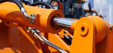
Hydraulic Cylinder Manufacturers
Complete hydraulic cylinder component portfolios — barrel boring and honing, piston machining, rod turning and chrome coordination, seal gland boring, end cap matched-pair machining, tie rod matched-length sets, and mounting hardware — with prototype-to-volume manufacturing continuity. Complete matched kits per cylinder build slot delivered synchronized to assembly schedules. Volume programs at 500,000+ annual units with PPAP Level 3 documentation and blanket order monthly delivery.
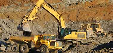
Mobile Equipment OEMs
Precision hydraulic cylinder components for excavator, loader, and agricultural machinery cylinders — 4140 steel pistons with hard chrome OD; E355 barrels with honed bores for abrasive field environments; aluminum 6061-T6 pistons and end caps for weight-critical boom and arm actuators. Supply chain programs at 100,000+ annual unit volumes with dedicated MAZAK mill-turn capacity for mobile OEM cylinder programs.

Industrial Automation Builders
Close-clearance servo hydraulic cylinder components — barrels honed to H7 class ±0.005mm for precision motion cylinders in press, forming, and material handling automation; pistons with compact seal and T-seal groove configurations at ±0.020mm; seal glands with rod bearing bores at ±0.005mm for precise rod guidance. Hard chrome rod programs for long-cycle press cylinder durability. Matched kit verification for automation line assembly efficiency.
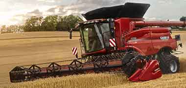
Agricultural Machinery Producers
Hydraulic cylinder components for tractor lift cylinders, harvester header actuators, and sprayer boom cylinders — E355 barrels with honed bores and hard chrome bore plating for corrosion resistance in field environments; bronze C93200 self-lubricating pistons for cylinders in dusty agricultural conditions where conventional elastomeric seals fail; 1045 tie rods with matched-length sets for reliable field service. Volume production at 50,000+ annual units.

Construction Equipment Companies
High-pressure hydraulic cylinder components for crane, piling, and tunneling equipment — E355 barrels rated to 350 bar; 4140 steel pistons with induction-hardened OD surfaces for maximum wear resistance; 4140 QT tie rods for heavy-duty pre-tension; composite piston assemblies with PTFE wear rings for high-load, high-speed cylinder applications. End caps in ductile iron EN-GJS-500 for pressure containment at maximum operating loads.
Marine Hydraulic System Manufacturers
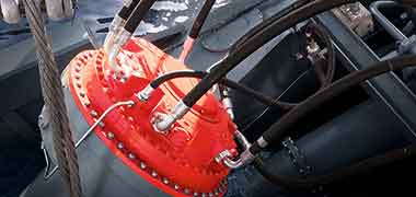
316L stainless steel hydraulic cylinder components for marine winch, steering, and deck machinery cylinders exposed to seawater and salt spray — corrosion resistance equivalent to 304 stainless without chrome plating. Passivation ASTM A967 mandatory post-machining on all stainless components. 316L barrels, pistons, rods, seal glands, end caps, and mounting hardware as complete matched marine cylinder kits. Pressure rating to 700 bar for deep-sea hydraulic systems.
Hydraulic Cylinder Components
Process & Capabilities
CNCPioneer's process combines 66+ MAZAK mill-turn centers with boring, honing, live tooling, sub-spindle transfer and documented inspection for cylinder components that must align after assembly.
24-Hour Hydraulic Cylinder DFM & Engineering Review
Single-setup concentricity feasibility for every component · Barrel bore specification review against piston OD running clearance and seal manufacturer tables · Seal groove standard identification and dimension pre-loading from ISO 5597, JIS B8354, DIN 24336 catalogs · Rod OD specification against seal gland seal bore and rod seal catalog · End cap tie rod hole pattern feasibility and matched-pair machining strategy · Material selection for pressure class, corrosion environment, and mass target · Chrome and anodize allowance planning · Volume production cost optimization specific to hydraulic cylinder geometry.
Barrel Boring, Honing & Port Machining
Barrel boring on MAZAK mill-turn to ±0.005–0.010mm diameter; honing on precision honing machine to Ra 0.2–0.4μm with 45–60° cross-hatch pattern and ±0.005mm cylindricity; end facing and thread or weld preparation on MAZAK. Port machining: hydraulic ports (G1/4 through G2 BSP, SAE ORB, or NPT) at C-axis indexed positions from bore datum ±0.100mm. Bore size range Ø20mm through Ø800mm standard; above Ø800mm on special program. Hard chrome internal bore plating coordination for high-wear applications.
Single-Setup Piston OD + Groove Machining
Standard piston sequence on MAZAK sub-spindle platforms: face left end; center drill → OD rough turn to +0.3mm stock → bore center bore or internal thread rough → thermal stabilization → OD finish turn to ±0.010mm → all seal grooves in sequence: single plunge per groove (±0.020mm width and depth) → in-process groove measurement → OD finish pass with CBN or PCD insert at final diameter ±0.005mm; Ra 0.2–0.4μm → internal thread finish → part-off / sub-spindle right face machining. 100% groove dimensional verification per groove per piston.
Piston Rod Turning + Chrome Coordination
Rod turning on MAZAK to ±0.010mm pre-chrome; rod end thread turning with concentricity to OD ±0.005mm; straightness verification ±0.05mm/1,000mm. Hard chrome coordination through qualified plating partners: chromium electrodeposit 0.020–0.040mm thickness; post-chrome grinding to ±0.005mm OD and Ra 0.05–0.1μm superfinish. Integrated supply: procure, machine, chrome, grind, inspect, ship as one rod delivery program. 17-4PH and 316L rod programs without chrome plating — precision ground and polished to Ra 0.1μm.
Seal Gland & End Cap Single-Setup Machining
Seal gland: all seal cavity bores, rod bore, and external mounting thread from one datum on MAZAK mill-turn; bore concentricity ±0.005mm; all seal cavity dimensions ±0.005mm; thread OD ±0.005mm from bore datum. End caps: all bores from common barrel bore datum; port threads at C-axis indexed positions ±0.010mm from bore center; tie rod holes C-axis drilled simultaneously from bore datum ±0.010mm true position; mounting feature bores concentric to cylinder bore ±0.010mm; face flatness 0.010mm. Matched front/rear cap set verification: tie rod hole patterns CMM-verified on both caps simultaneously.
Matched Cylinder Kit Assembly & Documentation
Complete cylinder kit programs: all seven component types coordinated under one program with inter-component compatibility verification before shipment. Barrel bore × piston OD running clearance confirmed; rod OD × seal gland seal bore running clearance confirmed; front/rear cap tie rod hole pattern match verified within ±0.020mm. Kit packaging: all components packaged as complete cylinder assembly kit with CMM compatibility report. Documentation: CoC, CMM report per component, profilometry records, material certificates, chrome plating records, thread gauge records, PPAP Level 3 for OEM programs.
Materials for Hydraulic
Cylinder Components
Material selection follows pressure class, corrosion exposure, wear, mass and machinability. Common grades include 4140, 1045, E355, ductile iron, 6061-T6, 316L, 17-4PH and bronze, with lot-level material verification.
E355 / ASTM A519 DOM Tube
Cold-drawn seamless steel tube — the standard cylinder barrel material for most hydraulic cylinders. Cold-drawn process ensures uniform bore geometry minimizing honing stock removal; surface-quality bore from drawing process. North American equivalent: ASTM A519 1026 DOM mechanical tubing with smooth bore. Standard carbon steel barrels used unhardened at up to 200 bar; above 200 bar and in abrasive environments, induction-hardened bore or hard chrome bore plating is specified for extended bore service life. Bore size range Ø20–800mm.
Ck45 (1045) + Hard Chrome
Standard hydraulic cylinder rod steel — 600 MPa yield; bright-turned and ground from precision ground bar stock; hard chrome plated 0.020–0.040mm then superfinished to Ra 0.05–0.1μm. Chrome provides HV 900+ OD hardness and mirror surface finish for rod seal contact. Rod OD tolerance before chrome: ±0.010mm (h8); post-chrome, post-grind: ±0.005mm (h6). Straightness ±0.05mm/1,000mm. CNCPioneer coordinates the complete turn + chrome + grind sequence as one integrated program.
Steel 4140 Alloy Steel
The default hydraulic piston material — providing the combination of strength, machinability, and case-hardenability that most industrial and mobile hydraulic piston applications require. Yield strength: 655 MPa (normalized); 900–1,000 MPa (quench + temper to HRC 28–34). Machinability: 65% of free-machining 1212. Surface hardness options: through-hardened HRC 28–34 for service wear resistance; induction-hardened OD surface HRC 54–60 for maximum wear resistance with tough core. Hard chrome plating: standard substrate for hard chrome OD plating (0.025–0.050mm chrome).
Steel 17-4PH H900 Stainless
Yield strength: 1,310 MPa (H900 precipitation hardened condition); HRC 44–47 — provides adequate OD wear resistance for steel barrel bore running without chrome plating. Corrosion resistance equivalent to 304 stainless in marine and mild chemical environments. Machined in solution-annealed condition, then precipitation hardened to H900 — minimizing distortion of precision groove dimensions during aging treatment. Post-aging dimensional change: ±0.003–0.008mm on piston OD — machined slightly undersize accounting for predictable aging growth. Also used for piston rods where chrome plating is unacceptable.
Ductile Iron EN-GJS-500
Standard end cap material for most industrial hydraulic cylinders — adequate yield (500 MPa) for pressure containment; excellent machinability for complex port and mounting geometries. Also used for seal glands where the combination of strength, machinability, and bearing compatibility is required. Forged carbon steel ASTM A105 or 1045 used where higher strength than ductile iron is required at minimum cost. 316L stainless for marine and chemical service end caps and seal glands.
Aluminum 6061-T6 & 7075-T6
6061-T6 aluminum for lightweight pistons, seal glands, and end caps in mobile and aerospace hydraulic cylinders — yield 276 MPa; 1/3 density of steel. Type III hard anodize (HV 400+) on aluminum piston OD and gland bores provides wear resistance without steel mass penalty. 7075-T6 aluminum for lightweight mounting eyes and flanges — higher strength than 6061-T6 for structural mounting hardware where mass reduction is critical. Anodize growth allowance machined into dimensions; post-anodize verification by air gauge.
Surface Treatments for
Hydraulic Cylinder Components
Hydraulic cylinder components surface treatment selection addresses bore wear resistance (hard chrome bore plating), rod seal contact durability (hard chrome rod plating), corrosion resistance in chemical and marine environments (electroless nickel, passivation), wear protection for aluminum components (Type III hard anodize), and mild corrosion protection for storage (black oxide) — coating allowances are machined-in and verified post-treatment.
Hard Chrome Plating — ASTM B177
The standard surface treatment for 4140 steel piston rods and cylinder barrel bores — chromium electrodeposit 0.020–0.075mm thickness providing: surface hardness HV 800–1,000 (HRC 65–72) for seal contact wear resistance; surface finish Ra 0.05–0.2μm from chrome-plated and ground/superfinished surface; corrosion resistance in hydraulic oil and water-glycol fluid environments. Rod OD machined undersize by chrome thickness allowance ±0.010mm; post-chrome OD verified to ±0.005mm of target by 100% measurement. Barrel bore chrome plating for high-wear, high-cycle applications. CNCPioneer coordinates the complete chrome deposition + post-plate grind sequence as a program deliverable.
Electroless Nickel — MIL-C-26074
Uniform corrosion and wear protection for hydraulic cylinder components in chemical, food processing, and offshore environments where hard chrome corrosion resistance is insufficient. Hardness: HV 500 (as-deposited); HV 900+ (heat-treated to 400°C). Coating uniformity: ±0.003mm across complex groove geometry — no masking required at grooves. Dimensional allowance: ±0.008mm per side; machined dimensions adjusted accordingly. Post-plate air gauge verification on all journal and bore diameters confirms seal engagement compliance before lot release. Critical for seal-contact zones: smooth deposition surface reduces running-in wear against lip seals.
Type III Hard Anodize — MIL-A-8625 (Aluminum)
Mandatory wear protection for aluminum hydraulic cylinder components — pistons, seal glands, and end caps in mobile and aerospace applications. Hardness: HV 400+ for aluminum 6061-T6; HV 300+ for 7075-T6. Thickness: 0.025–0.050mm per side; machined dimensions incorporate anodize growth allowance. Seal groove masking mandatory during anodize to prevent dimensional growth within grooves that would reduce groove width below seal specification. Post-anodize air gauge verification confirms final bore dimensions within H6/H7 specification. Provides wear resistance at piston-to-barrel and gland-to-rod interfaces without steel mass penalty.
Passivation — ASTM A967 (Stainless Components)
Mandatory for all 17-4PH and 316L stainless hydraulic cylinder components — restores passive oxide layer at all machined surfaces. Zero dimensional change. Removes machining free iron, enhances the passive chromium oxide layer for maximum corrosion resistance across cylinder service life. Applied after all machining is complete on pistons, rods, seal glands, end caps, and mounting hardware — including cross-holes, grooves, threads, and bores machined in the MAZAK single-setup program; passivation liquid penetrates all internal features uniformly. Passivation certificates included in standard shipment documentation for every stainless hydraulic cylinder components program.
Black Oxide — Mild Corrosion Protection
Mild corrosion protection for short-term storage and shipping; removed by hydraulic oil on first filling cycle. Dimensional change ≤0.0002mm — no dimensional allowance required. Low-reflectance finish for hydraulic cylinder components in instrument-quality applications where bright steel surfaces create undesirable optical effects. Applied in conjunction with passivation on stainless component programs requiring both low reflectance and corrosion resistance. Cost-effective alternative to electroless nickel for low-load indoor hydraulic cylinder hardware where corrosion resistance is secondary to storage protection and optical suppression.
Nitriding — Case-Hardened Surface Without Distortion Risk
Ion or gas nitriding (HRC 58–62 surface, 0.1–0.3mm case depth) for hydraulic cylinder components requiring enhanced surface fatigue resistance without the distortion risk of through-hardening — achievable on 4140 and 17-4PH pistons and rods already finish-turned to near-final dimensions, with post-nitriding finish-grinding restoring ±0.005mm accuracy. Nitriding's shallow case depth and low process temperature (480–550°C) minimize dimensional distortion versus through hardening (800–900°C quench), making nitriding the fatigue-enhancement treatment of choice for components whose seal groove concentricity cannot absorb the ±0.010–0.030mm distortion typical of through hardening. CNCPioneer coordinates pre-nitriding machining, nitriding vendor, and post-nitriding grinding as a complete program deliverable.
All surface treatments on hydraulic cylinder components programs — hard chrome ASTM B177, electroless nickel MIL-C-26074, Type III hard anodize MIL-A-8625, passivation ASTM A967, black oxide, and nitriding — are documented with treatment certifications and post-treatment dimensional verification in the shipment package. Plating and coating allowances are machined-in to dimensions at the CNC stage and confirmed post-treatment by air gauge or laser micrometer — ensuring dimensional specifications are met in the final delivered condition. Treatment selection guidance and dimensional allowance calculation are included in CNCPioneer's 24-hour DFM review at no additional cost.
Quality Assurance for
Hydraulic Cylinder Components
Quality assurance covers honed barrel bores, piston seal grooves, rod OD and finish, end-cap tie-rod patterns, coating dimensions and matched-kit compatibility, with PPAP support for qualified OEM programs.
Engineering Contract Review & DFM
24-hour DFM review covering: barrel bore specification against piston OD running clearance and seal manufacturer tables; seal groove standard identification and dimension pre-loading from ISO/JIS/DIN catalogs; rod OD specification against seal gland seal bore and rod seal catalog; end cap tie rod hole pattern feasibility and matched-pair machining strategy; material selection for pressure class, corrosion environment, and mass target; chrome and anodize allowance planning; volume production cost optimization. All drawing ambiguities resolved before machining.
Material Verification
SII XRF composition confirmation on every material lot — E355/DOM barrel tube, 4140/17-4PH pistons, Ck45/316L rods, ductile iron/1045/Al end caps and glands, 1045/4140/316L tie rods confirmed before machining operations begin. Hardness verification post-aging (17-4PH H900: HRC 44–47) and post-heat-treatment (4140: HRC 28–34) — per lot before final machining. Bar stock OD and straightness incoming check before MAZAK loading. Full mill-certificate-to-shipment lot traceability on all components.
In-Process Component Machining Control
First-off laser micrometer and air gauge verification before batch release. Adaptive offset correction for tool-wear diameter drift maintaining ±0.005mm compliance without operator intervention. Barrel bore honing: in-process air gauge and profilometry confirming Ra 0.2–0.4μm and cross-hatch angle 45–60°. Piston groove width telescoping gauge at 3 positions per groove; groove depth depth micrometer per groove. Rod straightness verification ±0.05mm/1,000mm. End cap tie rod holes CMM-verified from bore datum. SPC Cpk ≥1.33 (≥1.67 on IATF special characteristics).
Final Inspection — 100% Critical Feature Verification
100% groove width and depth verification per groove per piston. 100% laser micrometer OD verification on all pistons and rods — every part, not sampled. CMM: barrel bore diameter and cylindricity; all piston groove positions, widths, and depths; rod OD diameter and straightness; end cap tie rod hole true positions; seal gland bore concentricity and cavity dimensions; mounting feature positions and perpendicularity. Profilometry: barrel bore Ra, piston OD Ra, rod OD Ra. Thread gauges: all threads. Eddy current: chrome or anodize thickness where specified.
Matched Cylinder Kit Compatibility Verification
For complete cylinder kit programs: inter-component compatibility verification before kit packaging — barrel bore versus piston OD running clearance confirmed within specification; rod OD versus seal gland seal bore running clearance confirmed; front and rear end cap tie rod hole patterns verified as matched pair within ±0.020mm. Each matched kit tagged with compatibility verification report enabling cylinder assembler to confirm all fits before assembly. For high-pressure cylinders where dimensional variation governs seal life and leakage performance, matched kit accuracy compresses variation below individual-tolerance outcomes.
Documentation Package
Certificate of Conformance · Laser micrometer OD diameter records (per lot) · Groove width and depth records (per groove per piston) · CMM dimensional report per component (concentricity, perpendicularity, shoulder positions, groove positions, tie rod true positions) · Profilometer surface finish records (barrel bore, piston OD, rod OD) · Thread gauge records · Material certifications with heat lot traceability · Heat treatment and coating certifications · Matched kit compatibility verification report · PPAP Level 3 for volume hydraulic cylinder OEM programs · FAIR per AS9102 for aerospace and defense programs · All records retained 20 years.
IATF 16949 Quality System for
Hydraulic Cylinder Components
CNCPioneer's IATF 16949 and AS9100D certified hydraulic cylinder components quality system addresses the four quality dimensions specific to precision cylinder manufacturing: barrel bore geometry governance, in-process groove dimensional verification, matched kit compatibility assurance, and PPAP Level 3 bridge to volume hydraulic cylinder supply chain qualification.
Barrel Bore Geometry Governance
Barrel bore diameter ±0.005mm and cylindricity ±0.005mm/300mm are structural guarantees — not outcomes of skilled operators achieving best possible results. CNCPioneer's MAZAK mill-turn boring followed by precision honing makes bore geometry a machine-process outcome rather than an operator-dependent outcome: the bore is bored to near-final dimension on a machine spindle, then honed to final geometry on a precision honing machine with in-process air gauge feedback. This structural guarantee extends through volume production without degradation — the ten-thousandth barrel is as round and straight as the first prototype.
- Bore diameter ±0.005mm structural
- Bore cylindricity ±0.005mm/300mm
- Cross-hatch honing 45–60° Ra 0.2–0.4μm
100% In-Process Groove Verification
Every hydraulic cylinder piston lot — every piston, every groove — receives in-process dimensional verification: telescoping gauge at 3 angular positions per groove for width; depth micrometer per groove for depth; and CMM groove network verification for concentricity. 100% verification rather than sampling eliminates the escape probability that sample-based inspection cannot eliminate when specification bandwidth is ±0.020mm and lot size ranges from 1 (prototype) to 100,000 (volume). This instrument suite resolves all three seal groove dimensions (width, depth, concentricity) that determine seal fit and hydraulic cylinder leakage performance.
- 100% groove width verification per groove per piston
- 100% groove depth verification per groove per piston
- CMM groove concentricity ±0.010mm per groove
Matched Kit Compatibility Assurance
CNCPioneer's matched cylinder kit verification is the differentiating quality capability for complete cylinder programs: inter-component compatibility is verified before shipment, not assumed from individual tolerances. Barrel bore × piston OD running clearance; rod OD × seal gland seal bore; front/rear cap tie rod hole pattern match — all confirmed by CMM and documented in the kit compatibility report. This verification eliminates the assembly interference, selective fitting, and rework that multi-supplier sourcing produces when individual tolerances stack unfavorably.
- Inter-component clearance verification per kit
- End cap tie rod pattern match ±0.020mm
- Compatibility report with every matched kit
PPAP Level 3 & Volume Supply Chain Qualification
PPAP Level 3 qualification for hydraulic cylinder OEM supply chains: design records, process flow (including single-setup sequence documentation for each component type), PFMEA (covering tool wear diameter drift, bore honing form failure, groove form failure, tie rod pattern mismatch), control plan, MSA Gage R&R on telescoping gauge, depth micrometer, and air gauge measurement systems, initial capability studies (Cpk ≥1.67 on IATF special characteristics: bore diameter, groove width, groove depth, rod OD, tie rod true position), and part submission warrant. Generated on the same MAZAK programs used in volume production. Volume blanket production at 500,000+ annual units per program.
- PPAP Level 3 for hydraulic cylinder OEM supply
- Cpk ≥ 1.67 on bore / groove / rod / tie rod
- MSA Gage R&R on all critical gauging systems
Hydraulic Cylinder Components FAQ
Common questions from hydraulic cylinder manufacturers and equipment OEMs comparing complete parts machining, matched kits, bore honing, chrome coordination and production documentation.
The complete hydraulic cylinder parts list by name: (1) Cylinder barrel — the main tube body; (2) Piston — the sliding pressure boundary element; (3) Piston rod — the output rod extending from the piston; (4) Seal gland — the rod seal and rod bearing housing at the rod exit; (5) Front end cap (rod end cap) — the closure at the rod end; (6) Rear end cap (cap end) — the closure at the non-rod end; (7) Tie rods — the tension rods clamping end caps; (8) Tie rod nuts — threaded fasteners tensioning the tie rods; (9) Hydraulic ports — fluid connection points (Port A at cap end; Port B at rod end); (10) Piston seals — O-rings, U-cups, or piston rings in piston OD grooves; (11) Rod seal — primary seal against piston rod OD in seal gland; (12) Rod wiper (dust seal) — outer seal removing contamination from rod on retraction; (13) Rod bearing (rod bushing) — bronze or PTFE bearing supporting rod in seal gland; (14) Barrel-to-cap O-rings — face seals at barrel-to-end-cap interfaces; (15) Mounting hardware — clevis, trunnion, flange, foot, or other machine interface components.
Hydraulic cylinder parts identification from a cross-section diagram follows this pattern: the outer tube is the barrel; the two end closures are the end caps (rear/cap end on the closed side, front/rod end on the side with the rod); the rod extending through the front end is the piston rod; the disc inside the barrel attached to the rod is the piston; the ring assembly through which the rod exits is the seal gland; the external rods connecting the two end caps are the tie rods with nuts; and the attachment hardware on the end caps is the mounting hardware. In longitudinal cross-section, seal grooves appear as rectangular recesses on the piston OD (containing O-ring cross-sections); the rod seal cavity appears as a stepped bore within the seal gland; hydraulic ports appear as radial bores through the end caps.
From maintenance and failure analysis data: (1) Piston seal leakage — 35% of cylinder failures; caused by seal groove dimensional errors, barrel bore surface roughness above Ra 0.4μm, or bore cylindricity below specification; (2) Rod seal leakage — 30% of cylinder failures; caused by rod OD surface roughness above Ra 0.2μm, rod chrome delamination, or rod wiper degradation allowing contamination to reach rod seal; (3) Barrel bore scoring — 20% of failures; caused by contamination entering through failed rod wiper, bore hardness insufficient for operating duty cycle; (4) End cap O-ring leakage — 10% of failures; caused by O-ring groove dimensional errors or barrel-to-cap face flatness above 0.020mm; (5) Tie rod fatigue — 5% of failures; caused by unmatched tie rod lengths producing unequal pre-tension and cyclic overloading of undertensioned rods. CNCPioneer's hydraulic cylinder components programs address each failure point through dimensional accuracy at the governing feature.
CNCPioneer performs inter-component compatibility verification before kit packaging for all complete cylinder kit programs. Barrel bore diameter is CMM-measured and matched against the piston OD from the same program to confirm running clearance within 0.050–0.100mm specification. Rod OD (post-chrome, post-grind) is measured and matched against the seal gland rod bore to confirm rod seal running clearance. Front and rear end cap tie rod hole patterns are CMM-verified on both caps simultaneously to confirm pattern match within ±0.020mm — preventing the assembly interference that occurs when independently sourced caps have tie rod hole patterns that do not align. Each matched kit is tagged with a compatibility verification report documenting all inter-component dimensional relationships, enabling the cylinder assembler to confirm all fits before assembly without trial fitting or rework.
Prototype timing depends on component complexity and treatment scope: standard barrels, pistons, seal glands and tie-rod sets typically require separate machining reviews, while rod chrome and grind programs add outside-treatment coordination. Complete matched kits are scheduled as one coordinated delivery. Production pricing and release timing are quoted after DFM review of bore, stroke, pressure, seal, material, inspection and annual quantity requirements.
Get a Quote for Hydraulic Cylinder Components
Submit your drawing or CAD model for individual hydraulic cylinder components, partial sets or complete matched kits and receive a 24-hour DFM and quote review. Include bore, stroke, operating pressure, seal type, mounting configuration, material preference and annual quantity for the most accurate recommendation.